
Custom assembly automation · Case study
Automatic M12 Screw Fastening for Metal Tubes
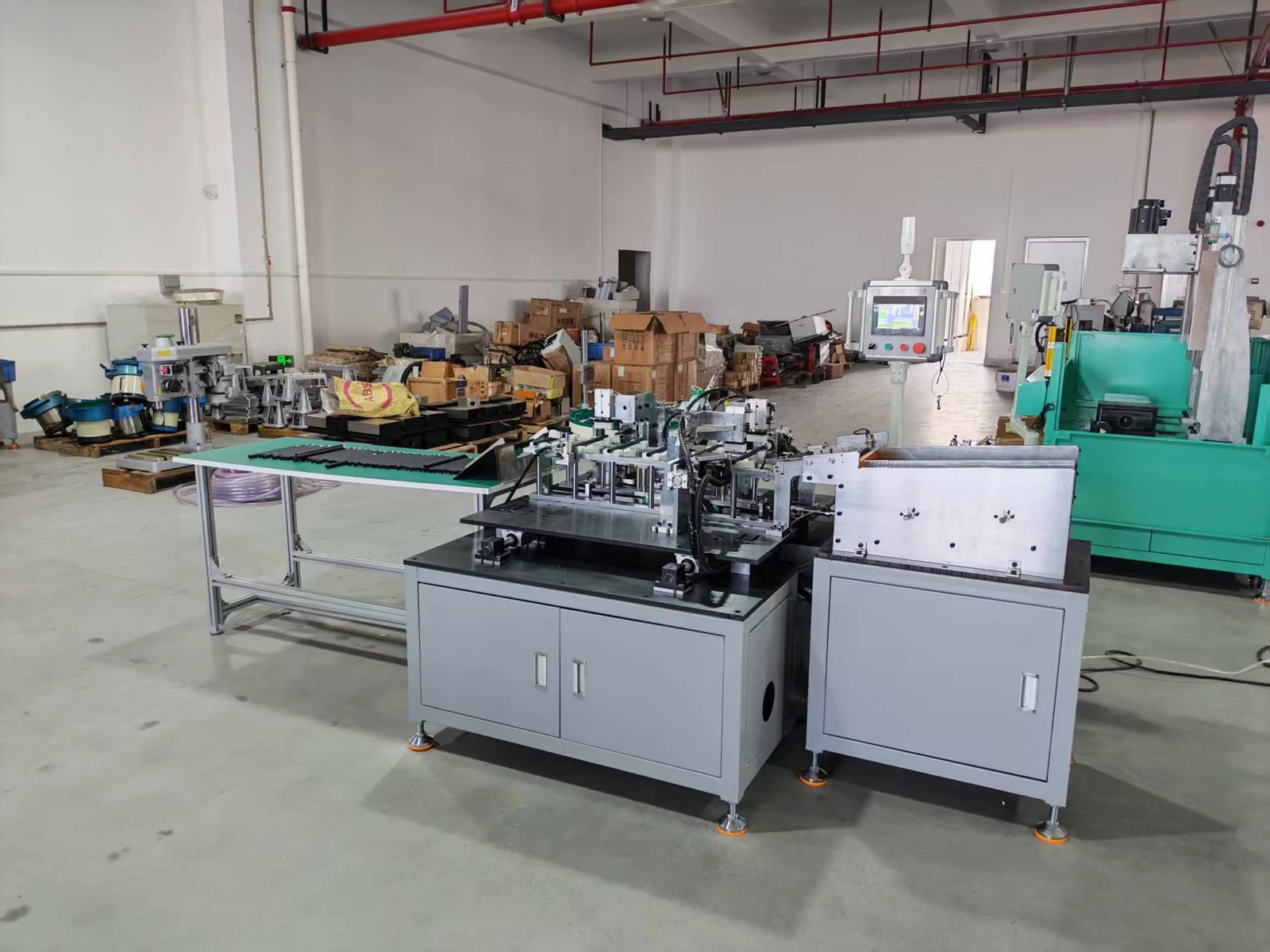
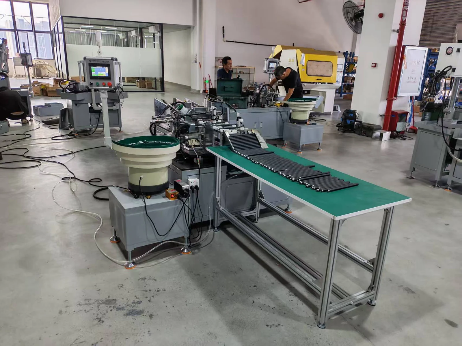
A fully automatic M12 screw fastening machine feeds metal tubes and threaded components, fastens them together and discharges the assemblies. Production and commissioning are complete, and the machine is ready for shipment.
 View full-size image ↗
Workshop videos
See the automatic cycle and machine layout
Two workshop videos show the completed machine in operation and the arrangement of its feeding and fastening equipment.
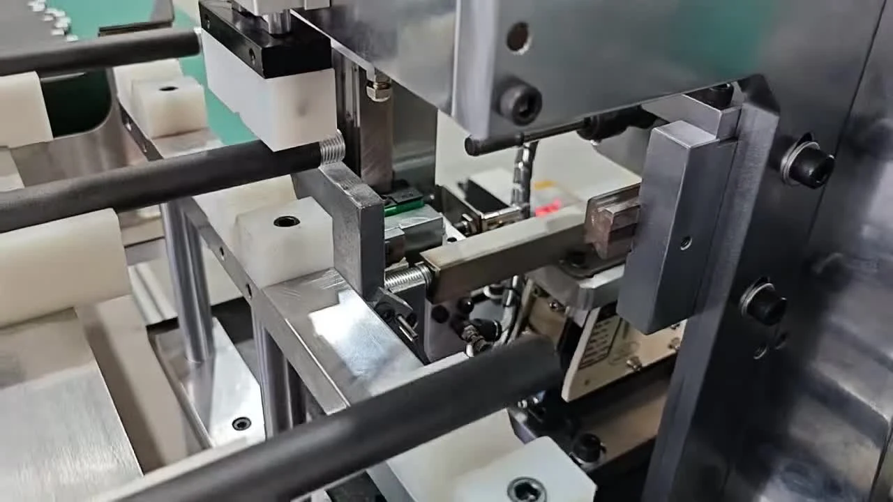
Automatic M12 assembly cycle
Watch tube feeding, threaded-component fastening and assembled-part discharge.
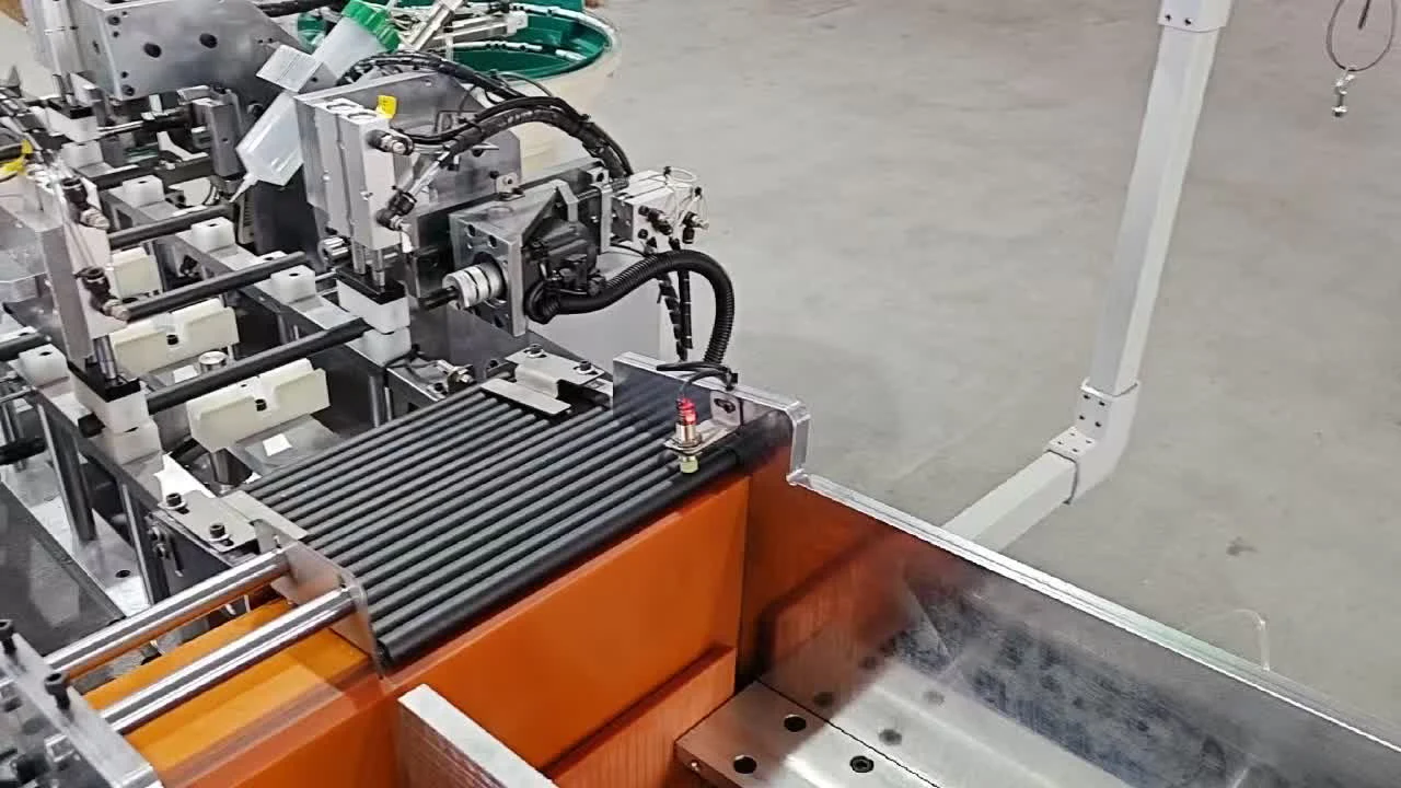
M12 screw fastening machine walkthrough
Inspect the equipment layout, component supply and tube-handling arrangement.
The assembly task
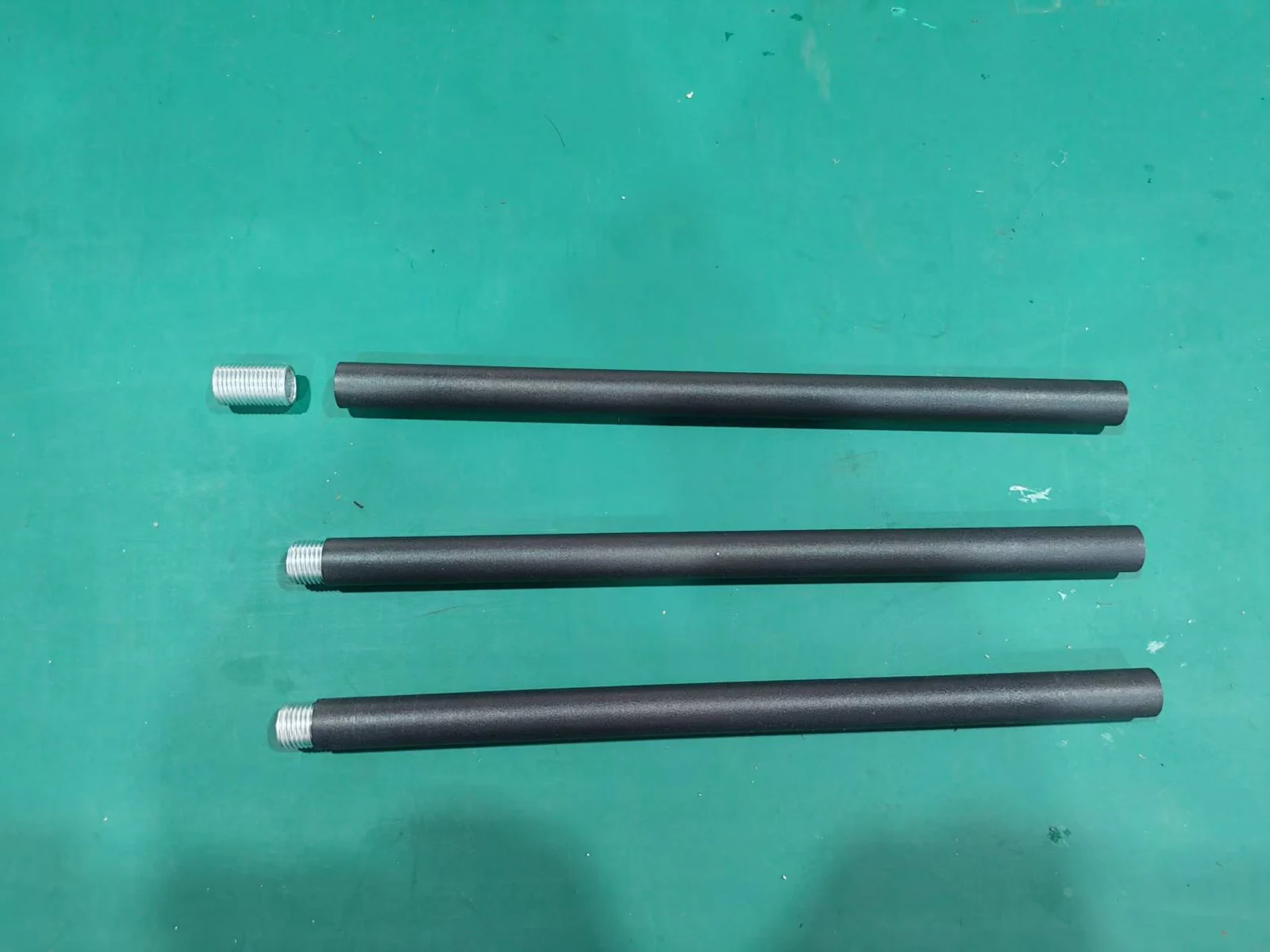
Fasten an M12 component into a 260 mm tube
The objective is to reduce manual assembly work and labor cost by automating the feeding, fastening and discharge sequence.
 View full-size image ↗
Defined around the two mating parts
The tube’s internal thread is already prepared before assembly. The machine installs the threaded component to a specified fastening depth of approximately 6 mm.
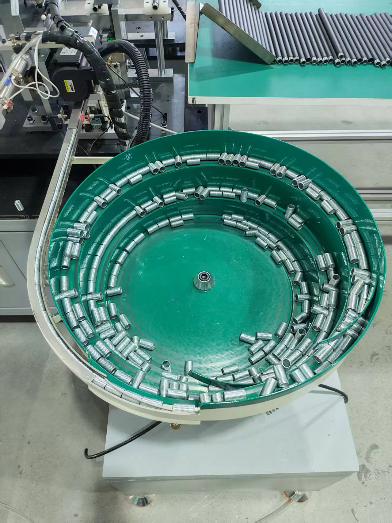
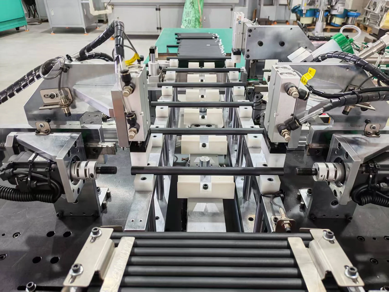
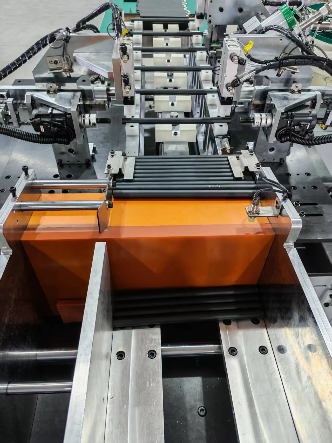
A vibratory bowl feeds the threaded components. A separate storage rack supplies tubes, while pneumatic transfer and a servo fastening drive carry out the assembly sequence under PLC control.
Production and commissioning have been completed. The machine is ready for shipment; the photographs and videos document this stage of the project.
Operating sequence
Load the supplies, then run automatic assembly
The operator starts the machine and periodically replenishes both part supplies.
Load and start
The operator loads threaded components into the vibratory bowl, puts tubes into the storage rack and starts the machine.
Feed and position
The bowl presents threaded components while the tube-feeding mechanism transfers tubes from the rack to the working position.
Fasten
The servo-driven mechanism fastens the M12 × 20 threaded component into the tube’s existing M12 internal thread.
Discharge and repeat
The assembled tube is discharged and the sequence repeats. The operator periodically refills the bowl and tube rack.
Project configuration
Dedicated feeding with servo fastening
The PLC coordinates the automatic sequence, with a touchscreen for operator control. The tube rack and vibratory bowl provide separate supplies for the two workpieces.
The listed capacities and dimensions describe this machine. A similar project starts with your tube and threaded-component drawings, feeding characteristics and required fastening result.
| Tube internal thread | M12 |
|---|---|
| Tube length | 260 mm |
| Threaded component designation | M12 × 20 |
| Specified fastening depth | Approximately 6 mm |
| Tube storage rack | 600 × 500 × 280 mm; approximately 200 tubes |
| Vibratory bowl | 530 mm diameter; approximately 450 threaded components |
| Fastening drive | 0.75 kW servo motor |
| Part transfer | Pneumatic push mechanism |
| Controls | PLC and touchscreen |
| Electrical supply | 380 V |
| Machine dimensions | Approximately 3350 × 1850 × 1700 mm |
| Machine weight | Approximately 300 kg |
Machine details
Inspect the feeding and fastening equipment
Open any workshop photograph at full size to examine the equipment.
 View full-size image ↗
Threaded component feeder
The 530 mm bowl holds approximately 450 threaded components for automatic feeding.
 View full-size image ↗
Servo fastening station
A 0.75 kW servo drive performs fastening at the dedicated working station.
 View full-size image ↗
Tube storage and feeding
The 600 × 500 × 280 mm storage rack holds approximately 200 tubes.
 View full-size image ↗
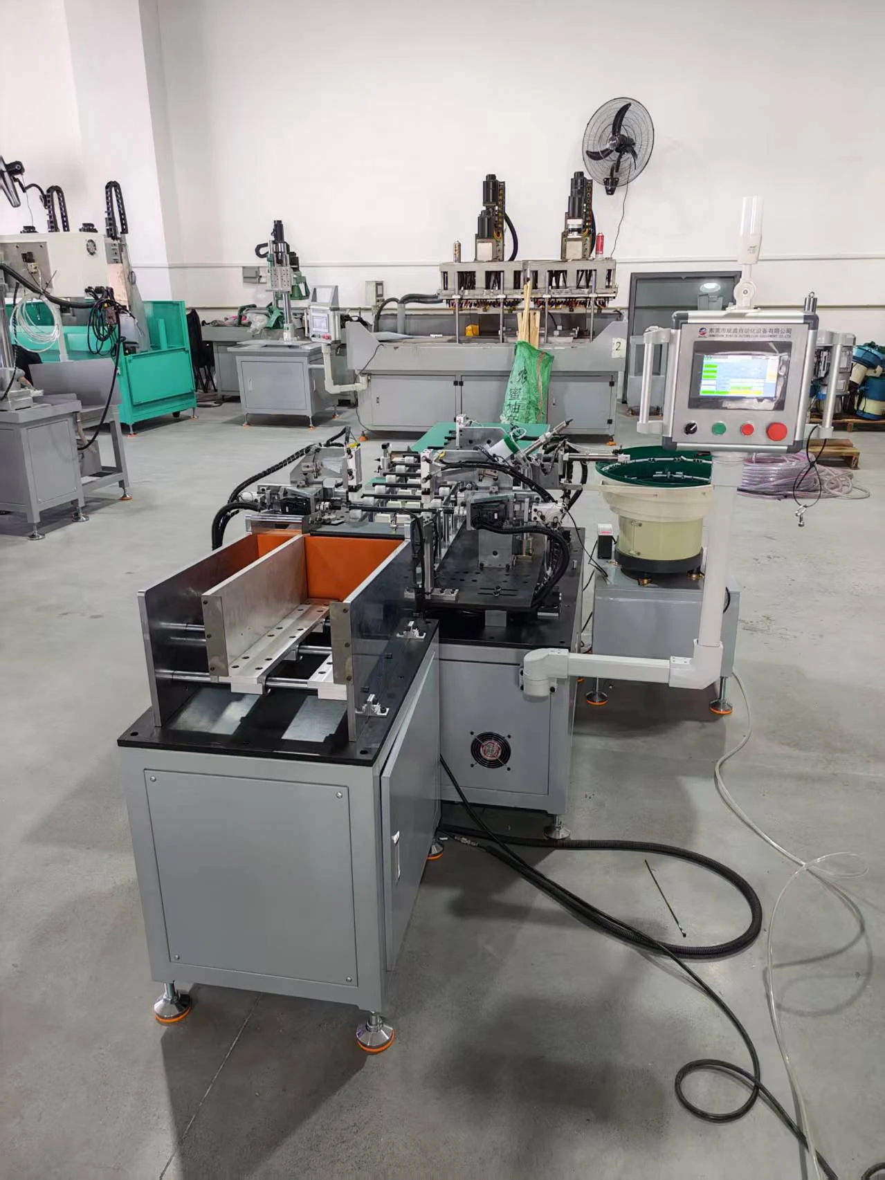
Machine side view
The completed machine before shipment, showing the assembly equipment from the side.
 View full-size image ↗
Plan your application
Have a similar tube assembly task?
A drawing is useful, but clear part photos and a description are enough to start the conversation.
Discuss Your PartUseful details to share
- Drawings or clear photos of the tube and threaded component
- Thread specification, fastening depth and any torque requirement
- Part variants, material and surfaces to protect
- Output target, loading method and acceptance checks
The selected machine or solution will be included in your inquiry.