
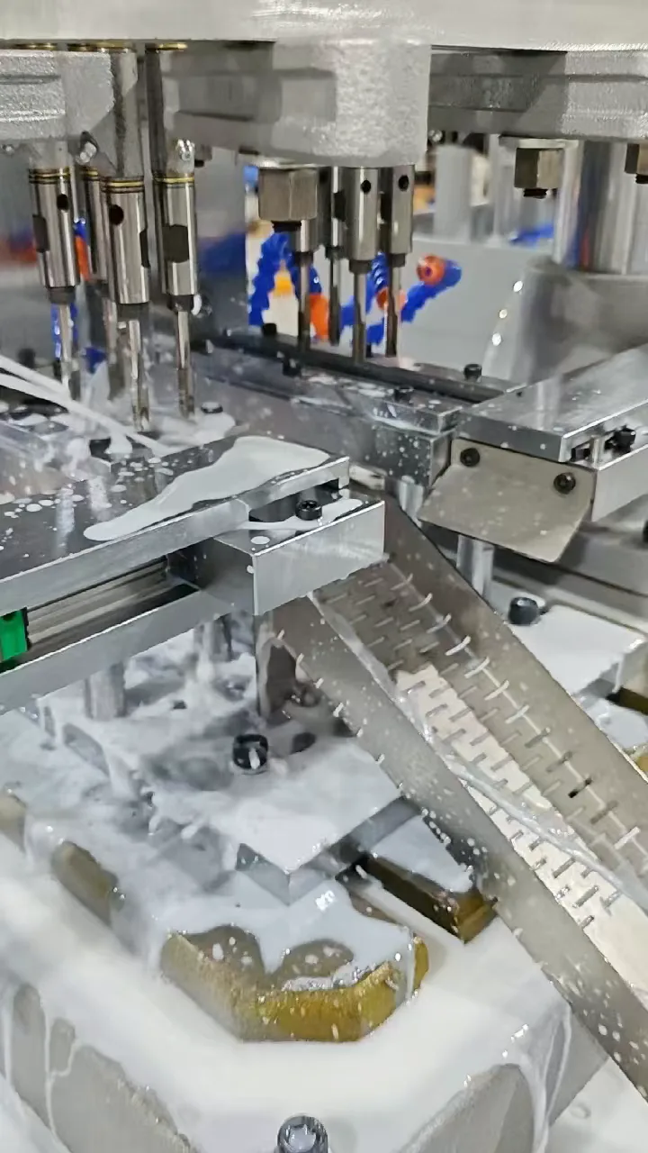
CUSTOM CONFIGURATION / VIDEO
M8 Tapping — Automatic Feed and Discharge
Watch the tapping area, pneumatic handling and discharge route on the custom machine. One part variant is processed at a time.
View project →Delivered project · Case study
One machine for two part variants, with four holes tapped together on the selected part. Dedicated pneumatic feed and discharge mechanisms connect magazine loading to finished-part collection. The machine has been delivered.
 View full-size image
The requirement
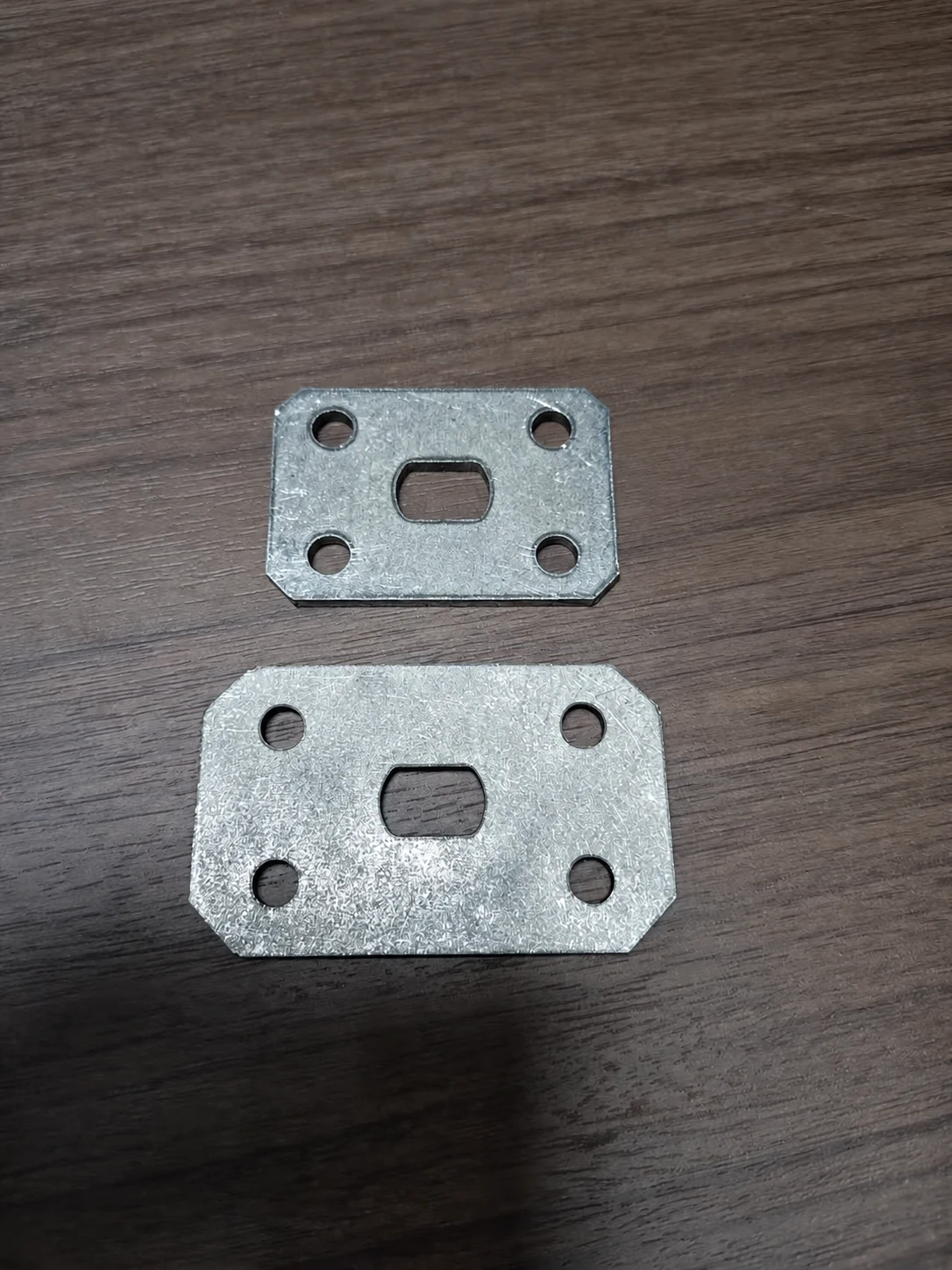
The customer needed one machine to accommodate the larger and smaller components, with automatic handling after the operator replenishes the selected magazine.
 View full-size image
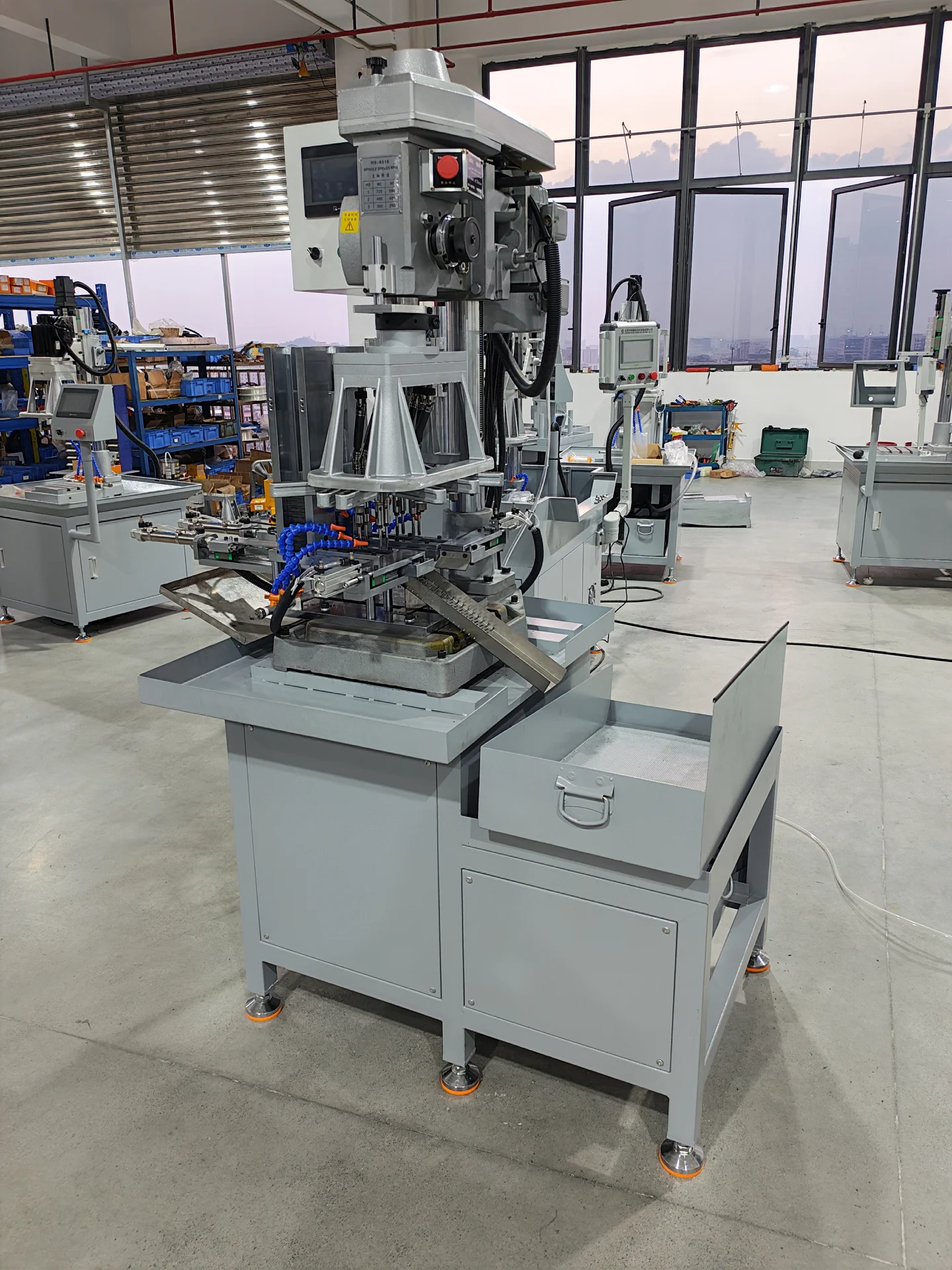
The heavy-duty multi-spindle head has eight tapping spindles arranged in two groups of four. One group corresponds to the larger component; the other corresponds to the smaller component.
Both part-specific fixture arrangements are integrated into one fixture assembly. Each variant has a separate storage magazine, feed track, pneumatic pusher and discharge cylinder.
One variant runs at a time. When the larger part is selected, the smaller-part feed path remains inactive, and vice versa. Changeover requires setup adjustments.
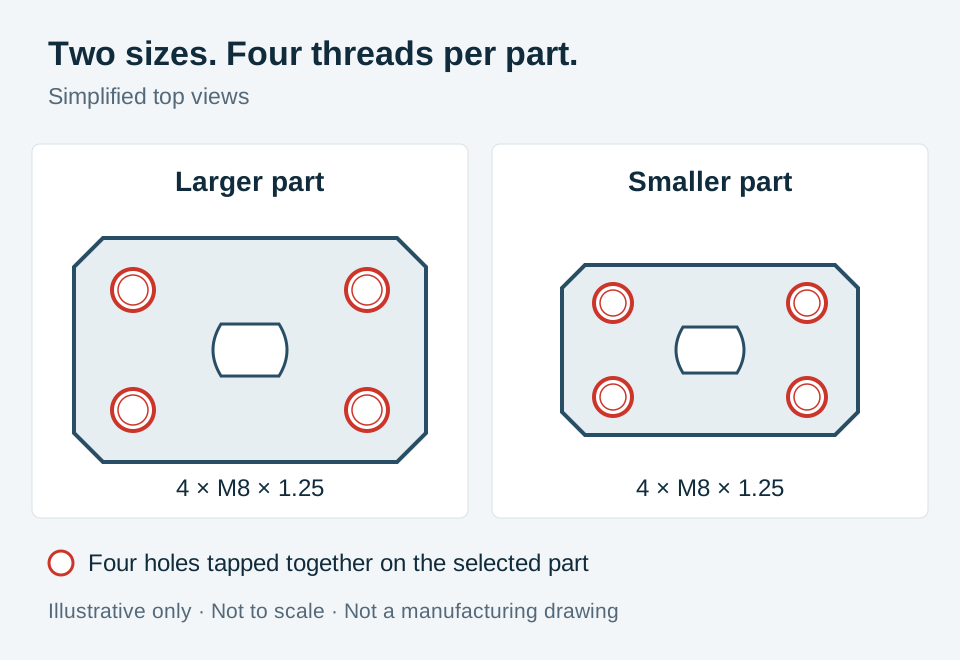 View full-size schematic
Simplified from the supplied part photographs. Customer identifiers, dimensions and tolerances are omitted. The outline and hole positions are illustrative, not to scale, and are not a manufacturing drawing.
Process route
Automatic handling covers the selected feed path. The operator still replenishes parts in batches and attends to production.
The operator replenishes the storage magazine for the selected part size.
A pneumatic pusher advances the part into the machining position.
The corresponding four-spindle group taps the M8 holes, with automatic cooling and chip flushing.
The discharge mechanism transfers the part onto the support and into a perforated tray that allows coolant to drain.
Project configuration
The 6516 gear-driven tapping machine, two four-spindle groups and dedicated feed paths form one integrated configuration. A PLC and touchscreen provide machine control and operator interaction.
| Tapping platform | 6516 gear-driven tapping machine |
|---|---|
| Multi-spindle layout | Two groups of four tapping spindles; one group in use at a time |
| Part variants | Two sheet-metal sizes, processed separately |
| Thread specification | Four M8 × 1.25 holes per part |
| Feeding and discharge | Dedicated pneumatic mechanisms for each variant |
| Controls | PLC and touchscreen |
| Coolant and collection | Automatic cooling, chip flushing and a perforated collection tray |
Handling comparison
Both arrangements tap four holes simultaneously. The comparison is with a four-spindle machine that requires manual loading and unloading.
| Process aspect | Four-spindle tapping with manual handling | This automatic feeding project |
|---|---|---|
| Tapping operation | Four holes tapped together | Four holes tapped together on the selected variant |
| Part handling | Operator loads and unloads each part | Pneumatic feed and discharge after batch magazine loading |
| Operator involvement | One operator continuously attends the machine | Periodic batch replenishment and production attention remain necessary |
| Cycle per part | Estimated 8–10 seconds | Target: 6–8 seconds for either size Includes feeding, tapping and discharge. Measured: 6.5 seconds for the large part; 6.2 seconds for the small part. |
Scroll horizontally to compare all columns on smaller screens.
The project target is 6–8 seconds per part for both sizes, including feeding and discharge. The measured cycle figures were supplied and confirmed by BINSING; the 8–10-second manual baseline remains an estimate, not a measured before-and-after trial. Cycle time does not represent sustained shift output: periodic replenishment and production attention remain necessary.
Equipment details
Open any photograph at full size to review the arrangement. Images retain their full frame so the feed paths and surrounding equipment remain visible.
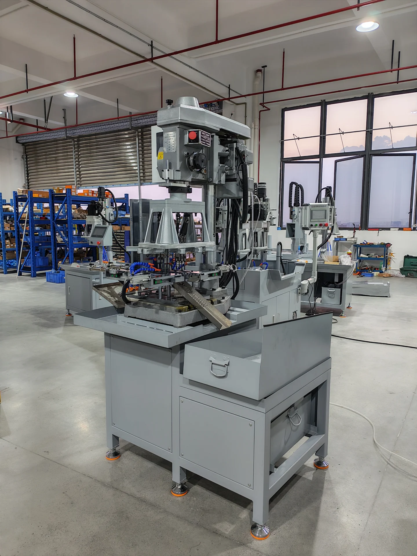 View full-size image
The tapping platform, feeding arrangement and finished-part collection share one machine layout.
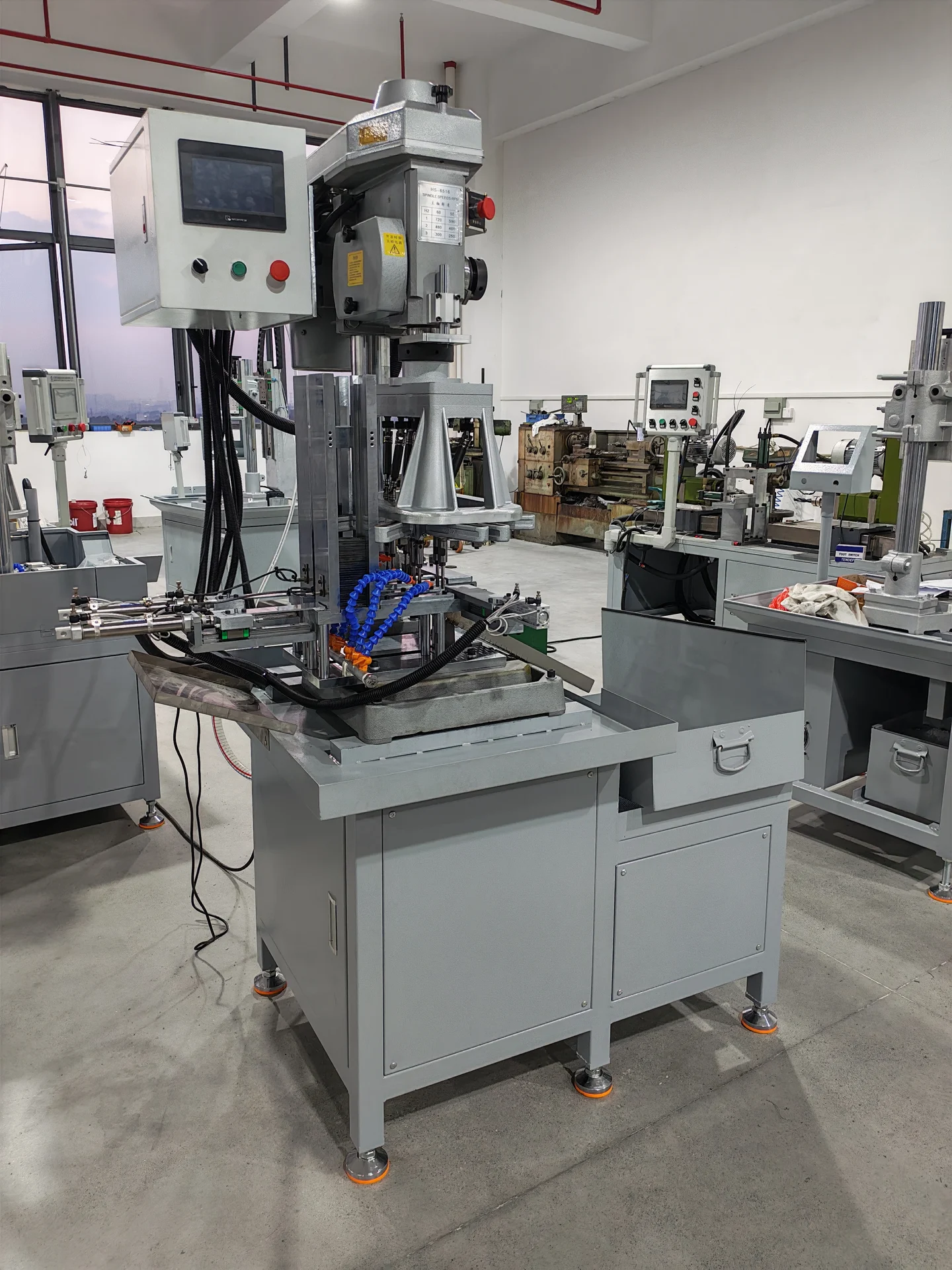 View full-size image
PLC and touchscreen controls support machine operation. Part-size changeover requires setup adjustments.
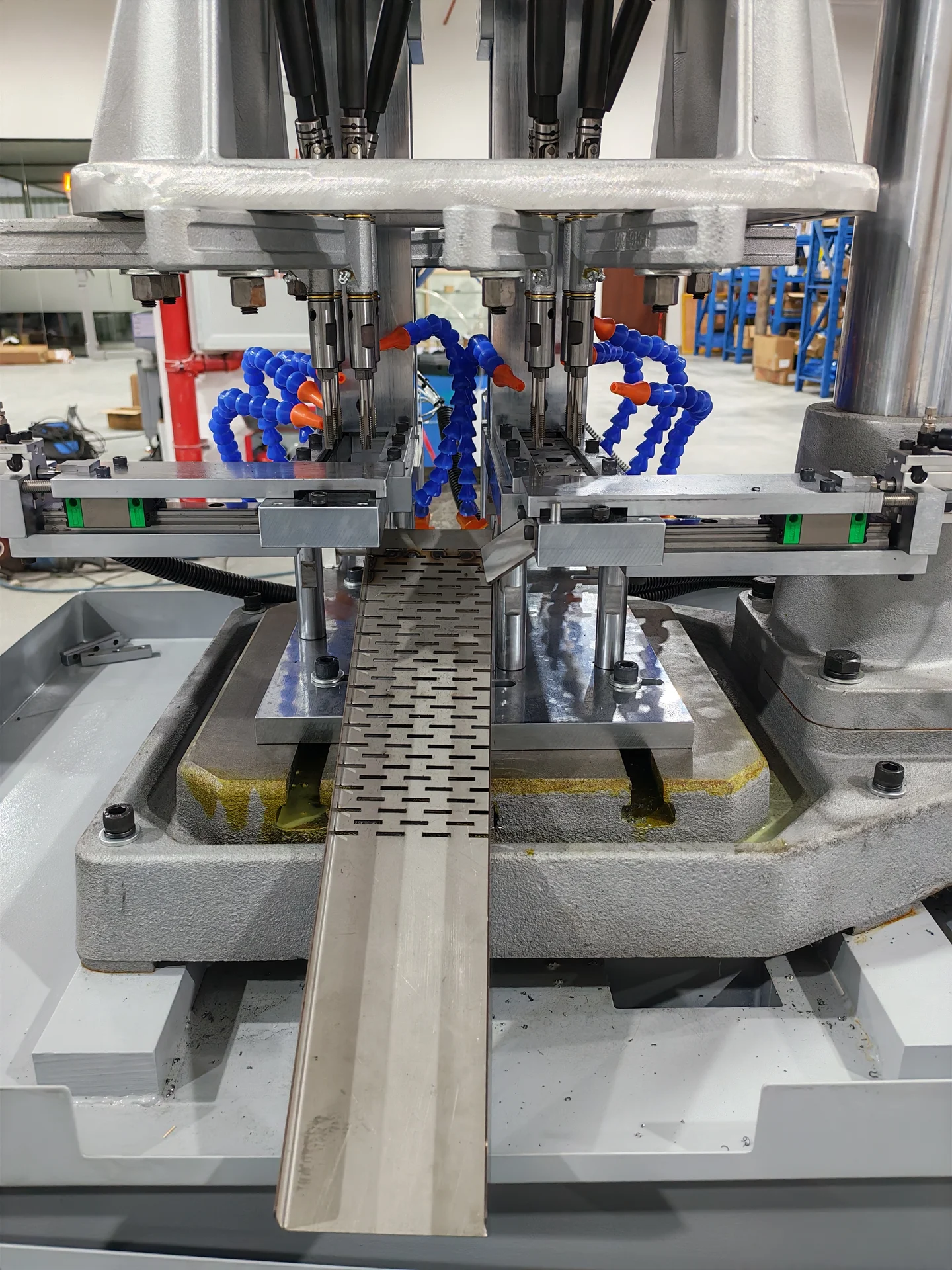 View full-size image
Each part size has its own storage magazine, feed track, pneumatic pusher and discharge mechanism.
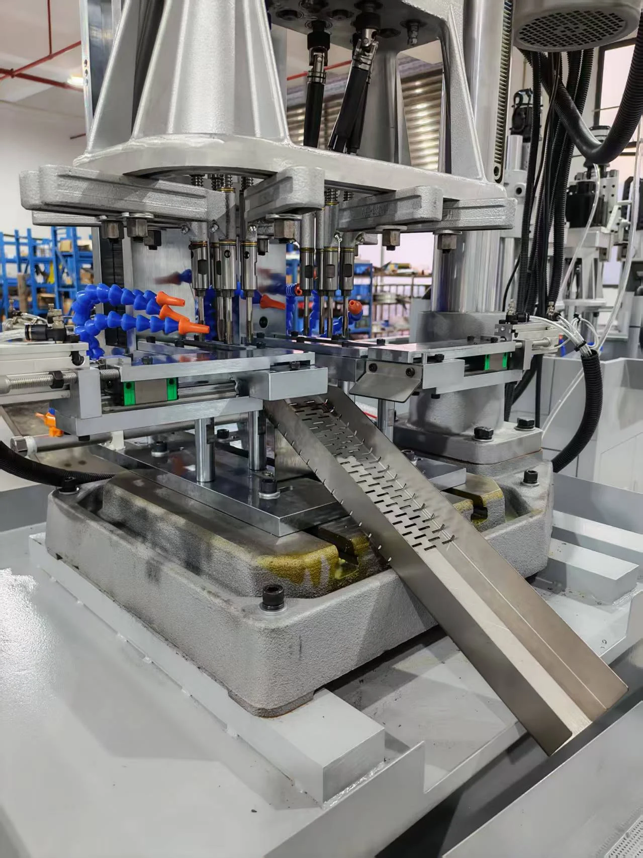 View full-size image
The discharge mechanism transfers the tapped part onto a support and into the draining collection tray.
Machine operation
Four views of the same project: automatic feeding and discharge, machining close-up, machine overview and finished-part collection. Select a video to play.
Watch the tapping area, pneumatic handling and discharge route on the custom machine. One part variant is processed at a time.
View project →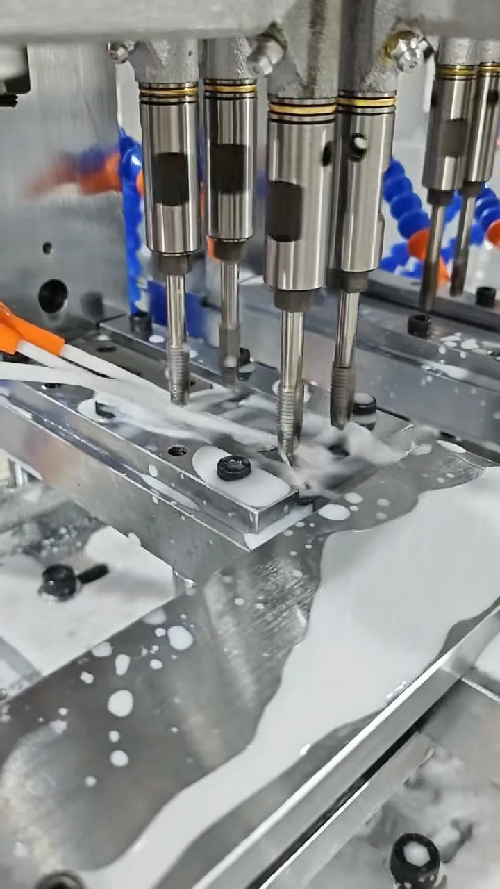
A closer view of the four-spindle tapping group, part fixture and coolant supply during operation.
View project →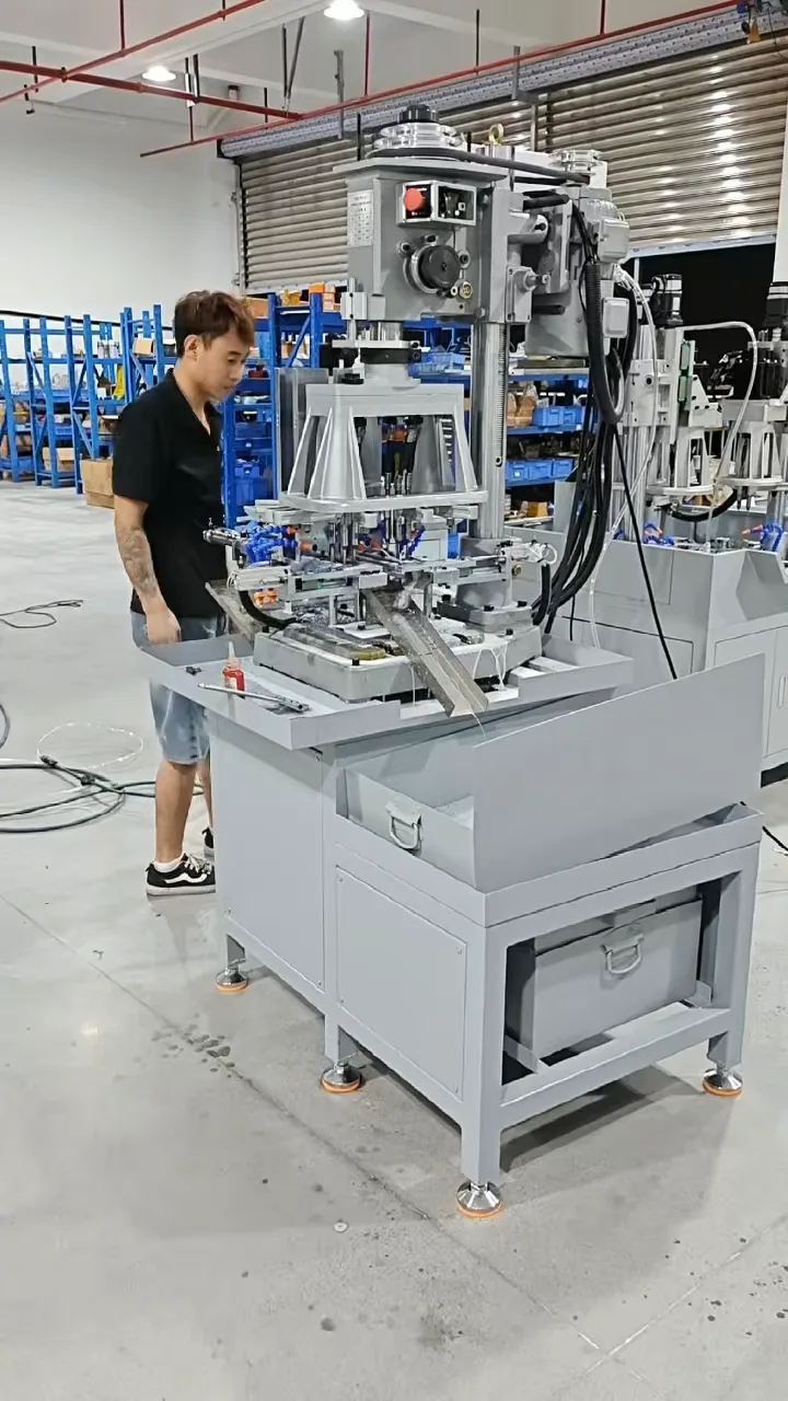
See the machining area and wider machine arrangement for the two-size sheet-metal tapping application.
View project →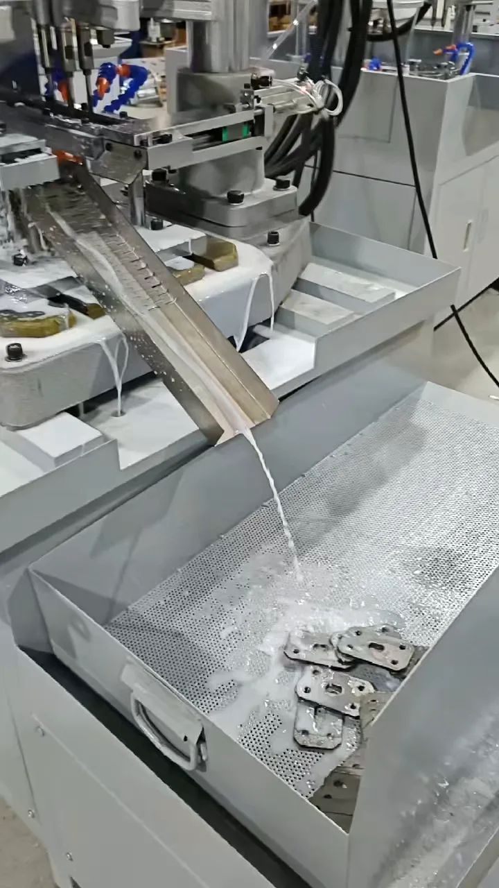
Follow the discharge support into the perforated collection tray used to collect parts and drain coolant.
View project →Plan your application
A drawing is useful, but clear part photos and a description are enough to start the conversation.
Discuss Your PartThe selected machine or solution will be included in your inquiry.
Related solutions