Explore equipment for your inquiry
Automatic Feeding & Tapping →Review the layout options and required part information to define the scope of a custom equipment inquiry.
What can be identified in the reference
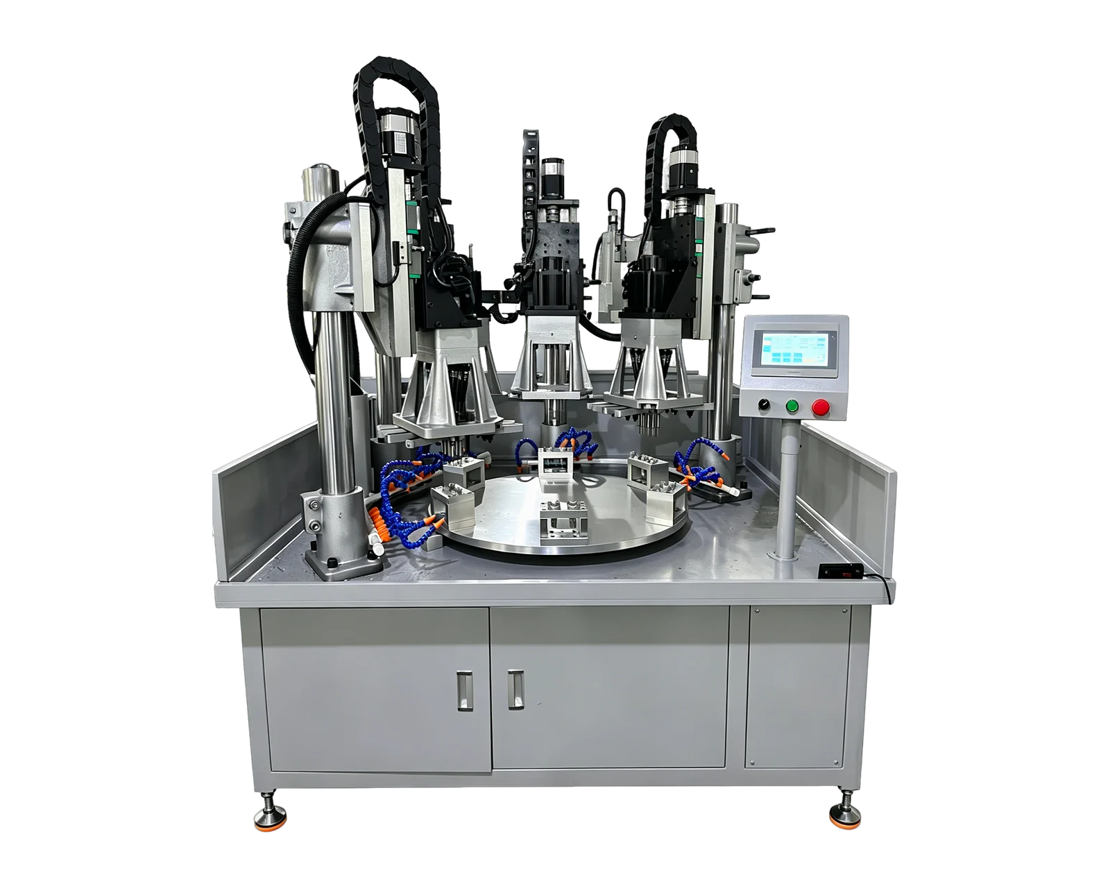
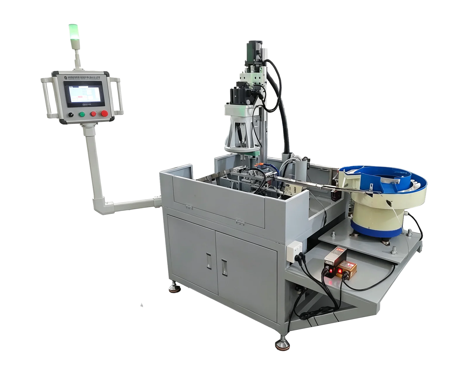
The published BINSING automatic feeding video is linked below. Reviewed frames from its original source show a bowl behind the machine, a narrow track leading toward the processing area, two upright machining heads and a compact circular workholding arrangement. A wider view includes a chute and collection container; a closer view shows the track interface, tooling area and coolant hoses.
These observations describe physical features. They do not identify the workpiece drawing, material batch, accepted thread condition or a verified assignment for every station. The visible collection container also cannot establish how many accepted pieces were produced during a particular interval. This article reviews the available footage as a starting point for requesting evidence; it is not a report of a completed feeding trial.
Follow the connections that a close-up cannot explain alone
Use the wide view to locate the bowl, track and machining area relative to each other. Then use the close view to identify the transfer boundary that needs explanation. Ask the supplier to describe how a part moves from the track into its processing position and how it reaches collection after the required operations. Do not assign an operation to a head simply because it is positioned above a particular location in one frame.
For your own application, request an annotated sequence with those boundaries marked. If coolant, tooling or the camera angle hides a transfer, request another view. A supplementary close-up can explain the mechanism, while an uninterrupted overview connects that explanation to the observed run. Keep the two purposes separate when reviewing edited demonstration footage.
Turn visible features into specific evidence requests
The worksheet below is an original review aid for this reference. It records questions left open by the available views. Its entries are proposed requests, not observations of faults or claims that the filmed machine includes particular monitoring functions.
Request a continuous interval, not an inferred production rate
Agree the recording boundary before an application trial: identify the parts and incoming condition, show the starting state, and record the selected interval without removing stoppages. Record refills, manual adjustments, cleared obstructions and restarts if they occur. Distinguish an operator action from a confirmed cause; the log should describe what happened before attributing it to feeding, machining or another part of the process.
Keep the recording duration and the counting interval aligned. An existing pile in a collection bin, repeated movement in a short clip or the number of visible nests cannot supply an accepted-parts-per-hour figure. If output is reported later, retain the underlying counts, exclusions and inspection basis. Agree the required duration and acceptance criteria for the actual application rather than treating this reference clip as a default test standard.
Use the event-log fields below beside the continuous recording. They are a proposed template for a future trial, not measurements from the published video. Retain events even when their cause is still unknown; an observed pause alone does not identify a feeder fault.
Connect the footage to parts that can be inspected
Give the trial a reference and keep the drawing revision, incoming sample identification, recording and event log together. Identify the collection associated with that run so that inspection findings can be traced to it. A smooth-looking transfer and an acceptable machined feature answer different questions; both may matter to the purchasing decision.
For a BINSING inquiry, share your drawing, representative part photos, incoming condition and required output, then identify which part of this reference arrangement interests you. Request a proposed evidence package covering the transfer and collection boundaries. That makes the next discussion concrete without presenting the published demonstration as proof of an unrecorded trial or a guarantee for another workpiece.