Explore equipment for your inquiry
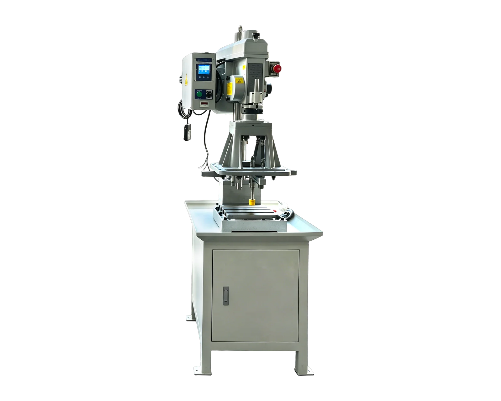
Dual-Servo Multi-Spindle Drilling & Tapping Machine →Review the published specifications and configuration options against your part drawing before requesting a quote.
Identify each surface by function before selecting a fixture
A copper component can contain a threaded mounting feature, a clearance hole and a broad contact face within a small area. Mark their different functions on the drawing rather than assuming the whole visible face has one acceptance rule. Ask the product owner to identify areas that may receive fixture contact, areas requiring protection and areas scheduled for later treatment.
The European Copper Institute's Copper for Busbars guide treats the condition of contact surfaces as part of joint performance. The purchasing implication here is limited: retain the approved contact-face requirements throughout the machining handover. This article does not specify joint design, contact pressure, electrical ratings or an installation procedure, and a machine trial cannot substitute for those engineering decisions.
Identify the actual copper and when the contact face is finished
Provide the copper designation and delivered condition, not only an electrical product name. Record whether the face arrives bare, plated, coated or protected for transport. Show whether machining occurs before or after final surface preparation. If the incoming sample differs from planned production, identify that difference before interpreting the trial.
Distinguish a visible mark from a defined nonconformance. The responsible quality or product owner should specify which observations require review and which checks determine acceptance. Do not introduce polishing, scraping, coating removal or a cleaning treatment merely to improve the appearance of a sample; those actions may change a surface whose condition is controlled elsewhere in the product process.
Give machining, fixture contact and verification their own columns
This original surface-zone template helps connect the equipment inquiry to the product drawing. Use actual face identifiers and approved requirements in the project version. A proposal for protective pads or a different locating area should be reviewed and demonstrated; its presence in a concept drawing is not evidence that the finished surface will be acceptable.
Check the contact face across the complete handling route
Record the same identified surfaces at receipt, after machining and at the agreed dispatch condition. If a mark appears only after collection, a photograph taken while the part remains in the fixture will not explain it. Include unloading and any part-to-part contact in the trial observation plan. Keep the route representative of production rather than protecting every demonstration sample by hand without recording that extra step.
Inspect the new feature and its surrounding face as separate items. A hole may satisfy its dimensional requirement while an adjacent protected surface needs review. Conversely, an attractive face does not demonstrate a conforming thread. Assign the necessary methods and responsibilities in advance so the trial report does not collapse these different results into a single general pass.
Close the gap between machining acceptance and product acceptance
In a hypothetical route, a copper part is machined before plating and later assembled into an electrical connection. The drilling supplier demonstrates the specified holes and edge condition; the finishing supplier accepts the incoming state; the product team verifies the completed assembly under its own requirements. If machining moves after plating, review the changed surface boundary rather than carrying over the earlier acceptance unchanged.
For a BINSING discussion, attach the material record, marked surface zones, machining scope and inspection responsibilities. Explain whether a completed contact face must be preserved or will be produced later. Request a trial that records the agreed surface and feature conditions. Electrical performance, coating suitability and final assembly qualification remain subject to the responsible product engineering review.