
Process planning · Custom solutions

End-Effector Adapter Drilling: Keep Tool-Side and Mounting-Side Interfaces Identifiable

Define the two sides of an end-effector adapter, controlled interface documents, hole ownership and component inspection before requesting machining equipment.

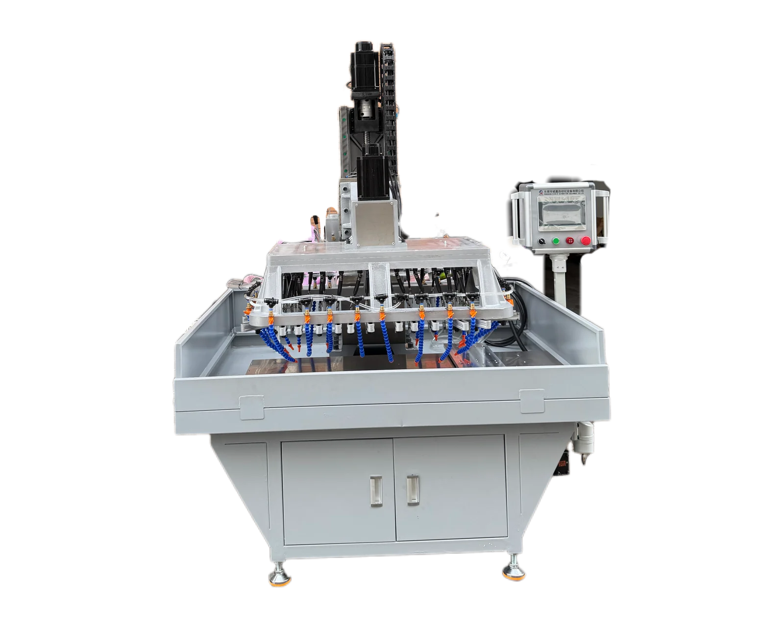
Servo-traverse drilling and tapping platform for reviewing adapter hole layouts

The short answer

Label the mounting side and tool side of the adapter consistently on drawings, photographs and inspection records. Identify each hole by its interface and feature number, including entry direction and existing condition. Assign responsibility for the released component drawing and any interface documents. Evaluate the requested adapter features separately from robot payload, motion performance or complete-system approval.

Explore equipment for your inquiry

Servo Traverse Multi-Spindle Drilling & Tapping Machine →

Review the published specifications and configuration options against your part drawing before requesting a quote.

1. Give both faces a stable name

An adapter may be described from the robot side in one document and from the tool side in another. Begin the inquiry with two clearly labeled views and a single component drawing revision. State which face each view shows. Include an orientation feature that can be recognized on the real part, so a photograph or trial record can be connected to the correct face without guessing.

Identify the item entering the proposed machine: a bare plate, a partly machined adapter or a component with installed inserts. Show existing pockets, central openings and completed reference surfaces. If a complete end-effector photograph accompanies the inquiry, label it as assembly context. It should not obscure the exact part or manufacturing stage for which the drilling and tapping proposal is requested.

2. Map hole identity to interface ownership

Use separate feature numbers for the two interfaces even when their patterns appear similar. Record entry direction and distinguish threaded holes from clearance, locating or other features. The buyer should identify the released source for each requirement and the person responsible for reconciling it with the adapter drawing. A supplier catalogue sketch is context until its role in the controlled requirement is established.

Adapter interface document map
ItemDocument referenceDecision to record
Mounting-side patternReleased interface and adapter feature IDsFace, orientation and drawing owner
Tool-side patternTool interface revision and feature IDsRequired holes and thread entry direction
Locating featureComponent requirement and incoming stateSeparate finishing and inspection scope
Central openingControlled outline and manufacturing stageExisting feature or separately supplied work
Installed insertInsert identity and assembly conditionInstallation responsibility and trial condition

3. Resolve drawing authority before quoting a pattern

Name the owner of the adapter drawing and the owners of the mating interfaces. If the tool supplier changes an attachment pattern, ask the adapter owner to issue or approve the corresponding component revision. Sending two incompatible interface files without a decision leaves the machine supplier unable to know which feature arrangement is intended. Preserve the original references and record the resolved requirement explicitly.

Separate an interface document supplied for explanation from one that defines acceptance. Where a buyer provides a mating flange or tool, state the specific purpose of that item. It may help explain orientation or support a defined fit check, but it does not by itself establish a complete inspection method. Agree how the adapter's requested holes and threads will be checked against the released component requirements.

4. Review changes on the side where they occur

Hypothetical purchasing example: two adapter versions share the mounting-side pattern, but the second tool requires a different tool-side thread arrangement. A trial completed for the first version provides evidence only for its recorded features and supplied condition. The buyer should identify the changed side and ask which machining, handling and inspection questions need another review. Similar overall shape is not a substitute for version coverage.

Keep the sample label tied to the complete adapter revision, not just the mounting interface name. Mark any temporary orientation labels used during the trial and state whether production parts may carry the same markings. If a revised drawing changes a locating feature or central opening, record that change even when it falls outside drilling and tapping. It may alter the incoming workpiece that the proposed arrangement must receive.

5. Ask for component evidence and a defined boundary

Provide expected demand by adapter version, representative samples available and the requested feature checks. Ask for a response that identifies covered interfaces, assumed incoming operations, proposed changeover scope and unresolved information. List insert installation, separate precision finishing and final assembly as their own responsibilities when relevant. This keeps the comparison focused on what each equipment proposal would actually deliver.

Email BINSING the adapter drawing, labeled face views and controlled interface register for a drilling and tapping review. Explain which requirements are approved and which still await the tool or integration team. The proposed component process should not be presented as proof of robot payload capacity, motion behavior or system certification. Those questions belong to separately defined engineering and system evaluation work with the responsible parties.

Prepare your part information

  • Mounting and tool faces labeled consistently
  • Hole IDs linked to their interface documents
  • Adapter drawing approval owner named
  • Incoming openings, references and inserts documented
  • Component inspection separated from system evaluation
Discuss adapter machining →

Common questions

Is an end-effector assembly drawing sufficient?

It gives context. The inquiry also needs the controlled adapter drawing, actual incoming condition and clearly identified requested features.

Who should resolve conflicting interface dimensions?

Identify the authorized component and interface owners. Their resolved requirement should be recorded before the machining scope is released.

Does an adapter machining trial confirm robot performance?

No. It provides evidence for the agreed component features. Robot and complete-system performance require separate evaluation.

Related equipment and project information

Define both interfaces of your adapter

Email the component drawing and labeled interface views for a review of the required holes and threads.

Discuss adapter machining ↗