Explore equipment for your inquiry
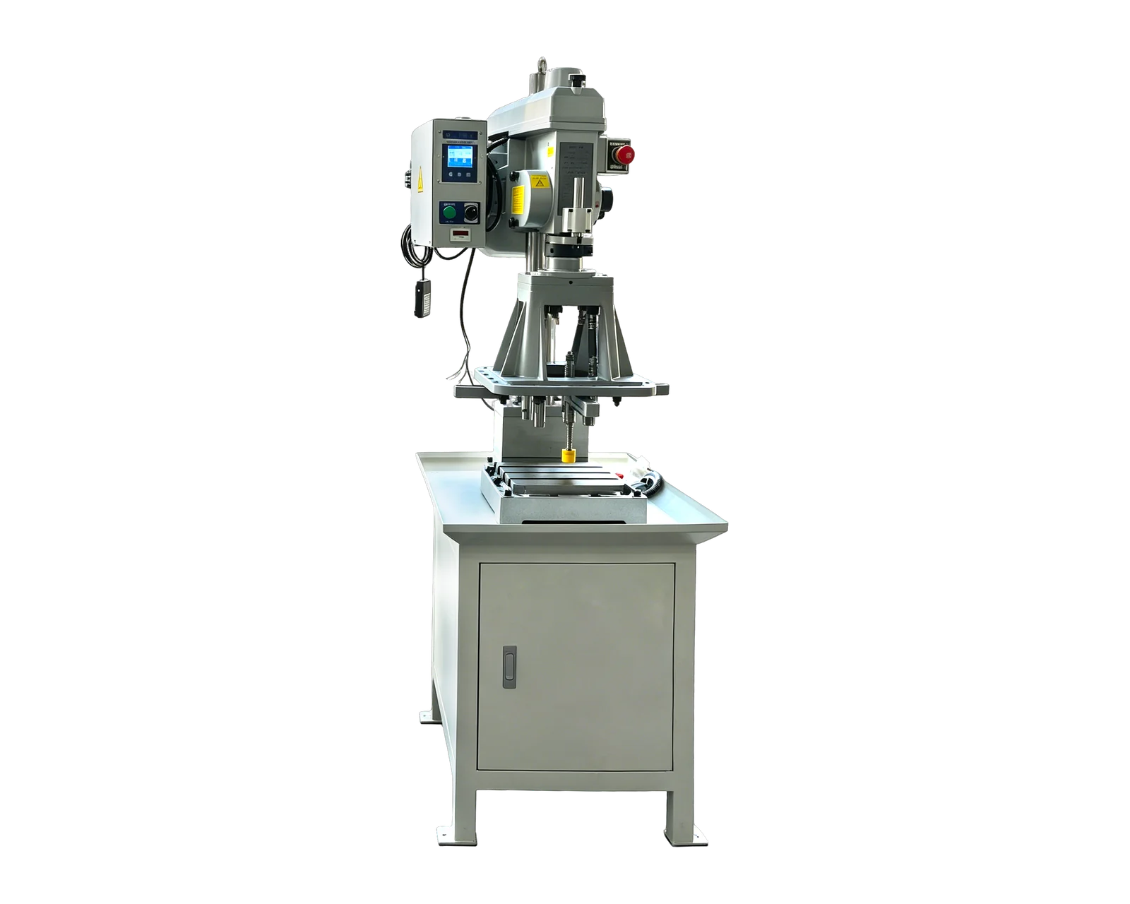
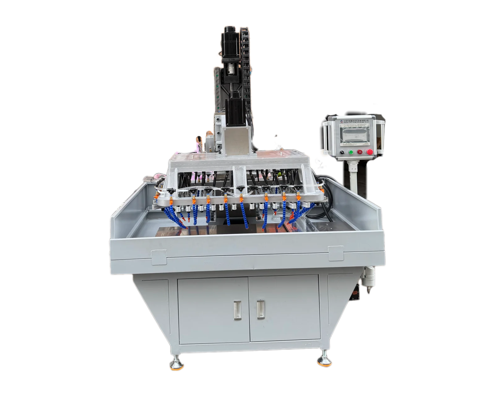
Servo Traverse Multi-Spindle Drilling & Tapping Machine →Review the published specifications and configuration options against your part drawing before requesting a quote.
1. Separate the disc from the mechanism name
The phrase indexing disc can refer to a component within a larger assembly. State that component's part number, material, revision and actual incoming condition. Identify existing center features, outside profiles, reference faces and any treatment. Mark the drilling or tapping operations requested. If teeth, slots or other forms are made by another process, show their status without adding them silently to the equipment inquiry.
Attach an assembly view only to explain the disc's role and orientation. A supplier needs the component requirements to review the hole work, not an assumption that the assembly name defines every feature. State whether the disc is loaded individually, with a hub or with other attached items. Identify those items and explain whether their presence is representative of normal production or only of the supplied sample.
2. Record zero and direction with every pattern
A circular arrangement needs more information than a hole count. Supply the controlled pattern definition and identify the face from which it is read. Where the drawing uses an angular zero or a designated reference feature, retain that convention in the inquiry and sample report. Ask the drawing owner to clarify an ambiguous view rather than letting a photograph become the unofficial angular reference.
3. Give mounting and functional holes different acceptance entries
A hole used to attach the disc and a hole used by another part of the indexing assembly may have different specified endpoints. Identify their functions for context, then quote the actual drawing requirements. If a functional hole needs a separate finishing operation, assign that operation and define the condition handed over after drilling. Do not treat every circular feature as an interchangeable drilling requirement.
Identify who checks the completed component features and who evaluates the assembled mechanism. If a pin, mating plate or other sample accompanies the disc, describe the intended check and its approved reference. A successful informal assembly attempt should not replace dimensional or other component checks required by the buyer. Conversely, a machining trial should not be expanded into an undefined mechanism performance test simply because a mating part is available.
4. Make mirrored views visible in sample records
Hypothetical purchasing example: a disc has an asymmetric functional hole arrangement and a separate mounting pattern. A rear-face photograph is supplied alongside a front-view drawing. Before the trial, the buyer labels both faces and links the image to the drawing's reference feature. The report then identifies which view defines the pattern, preventing a visually plausible mirrored layout from being treated as the approved arrangement.
For a family of discs, list pattern differences by revision and keep individual sample identities. A shared outside diameter does not establish that two parts use the same zero reference, hole function or entry face. Ask the supplier to identify the reviewed versions and remaining sample needs. When a reference feature changes, preserve earlier results against the original definition instead of relabeling them as evidence for the new drawing.
5. Request a proposal for the specified component work
Provide quantities by disc version, the supplied condition, the feature register and the required inspection evidence. Ask the supplier to state its proposed machining scope, assumed reference features and any separate finishing responsibilities. Include restrictions on marking finished faces if sample identity or orientation labels are needed. This produces a clearer comparison than asking for a machine to make indexing discs without defining the output.
Email BINSING the disc drawing, labeled front and rear views and pattern register for an application review. Explain whether the request covers drilling, tapping or a defined combination of operations. Manufacturing a component used in an indexing assembly is distinct from supplying the assembly itself. Keep mechanism design, positioning performance and final assembly evaluation within their own specified scope and responsible review.