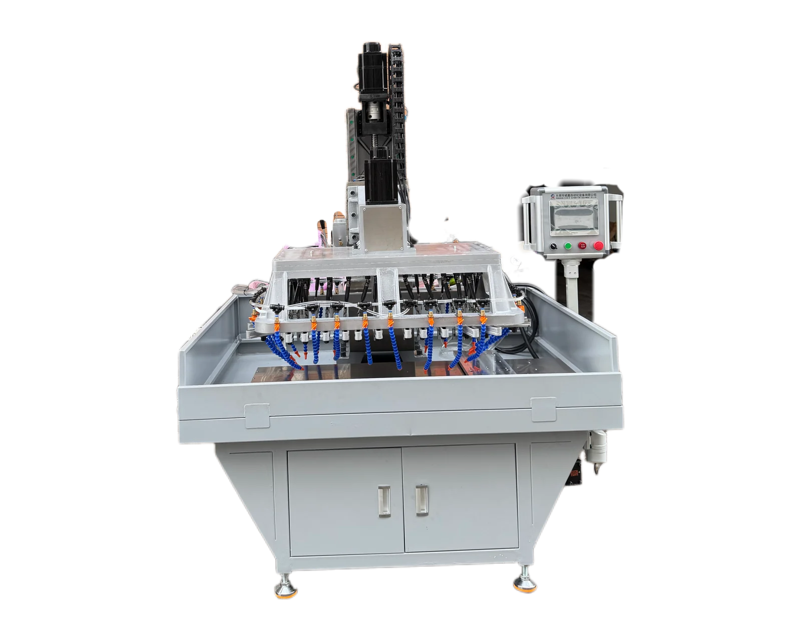
Explore equipment for your inquiry
Dual-Servo Multi-Spindle Drilling & Tapping Machine →Review the published specifications and configuration options against your part drawing before requesting a quote.
1. Define what the block contacts and how it is fixed
A machining stop block drawing can contain a workpiece-contact face, mounting faces, fixing holes and other locating features. Identify those roles explicitly rather than describing every machined surface as a datum. The equipment inquiry should name the holes and threads requested and show the surrounding features relevant to the supplied condition. Include the component number, material specification, revision and photographs of the actual incoming stage.
This inquiry concerns the individual stop components, not the full fixture base or the machining process that will later use them. If contact faces are finished by another operation, record that responsibility and the stage at which it occurs. If a block is supplied already finished, identify the faces that must be preserved.
2. Build a feature and set-position schedule
Use drawing identifiers for both features and members of a set. A left or right label alone can be ambiguous without a reference view, and two blocks may share an outside shape while carrying different fixing patterns. Keep the component-to-position relationship in a controlled schedule that can accompany the samples and the eventual inspection records.
3. Describe finishing order without assuming the fixture plan
State whether contact surfaces are finished before or after the drilling and tapping operation. If the route includes treatment or another finishing stage, identify it and assign any checks required after that stage. Ask the supplier to explain which incoming features the proposed arrangement assumes. The quotation should be based on the supplied condition that production will actually provide, not a fully finished demonstration part that bypasses the intended route.
For paired or grouped stops, state whether components must remain associated through machining and how that association is identified. Distinguish a buyer requirement to keep parts together from a confirmed machine handling feature. If automatic identification or set handling is requested, have it reviewed and quoted explicitly.
4. Keep similar set members from sharing the wrong evidence
Hypothetical purchasing example: a fixture uses three stop blocks with the same outline, but one position has a different fixing-thread arrangement. The buyer sends unmarked samples and a single general assembly view. Before a trial, link each sample to its component drawing and set position, then identify the distinct feature pattern. The supplier can assess the actual variants rather than demonstrate one block and imply coverage of all three.
Record which member each trial result represents and whether the remaining members still need evidence. If a later revision changes only the contact face, the responsible team should review the effect on the incoming references and acceptance requirements rather than automatically reusing the previous record. This example does not establish locating repeatability for the assembled fixture; it controls the identity and scope of the component evidence.
5. Specify the component handover and later set review
Agree the hole and thread inspection scope for each included component and keep its revision and set position visible in the report. Define any required identification marks or packaging relationship as separate deliverables for review. Name the party checking contact faces after later finishing and the party evaluating the completed set in its intended fixture. This makes it clear where machining acceptance ends and subsequent assembly review begins.
Email BINSING the stop block drawings, feature schedule, set-position map and incoming-stage photographs. Include expected quantities by component and identify representative trial samples. Request a proposal that distinguishes included operations, changeover assumptions and remaining evidence. Compare proposals against the same component boundaries.