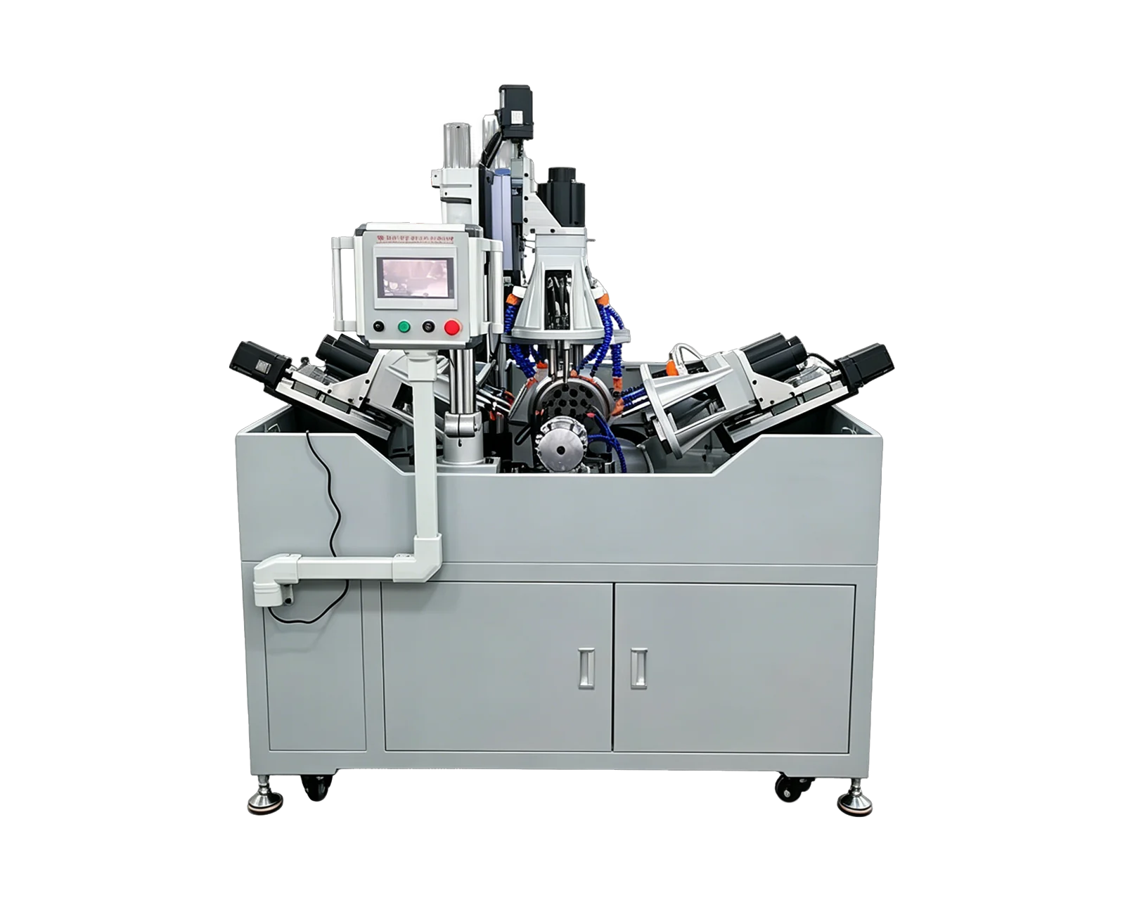
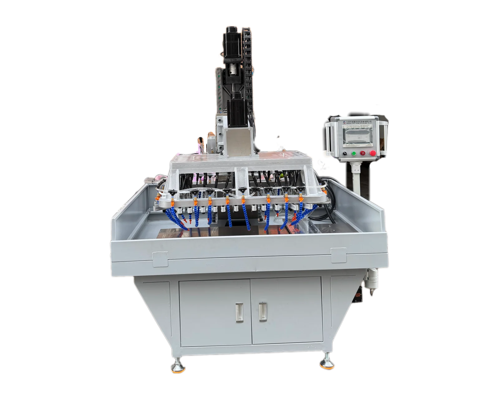
Explore equipment for your inquiry
Dual-Servo Multi-Spindle Drilling & Tapping Machine →Review the published specifications and configuration options against your part drawing before requesting a quote.
1. Describe the jaw at the point of loading
A finished clamping jaw photograph can conceal several separate manufacturing stages. Supply the drawing of the actual item entering the proposed machine, its material specification and its revision. State whether the contact profile, serrations, mounting face and any treatment already exist. Identify any later machining that will change the contact surface after the mounting holes are made.
Distinguish a jaw body from a replaceable pad or insert. If only the pad needs a threaded feature, do not describe the complete assembly as the workpiece. Mark which item will be loaded, which parts remain attached and which surfaces the buyer requires to be preserved. This gives the equipment review a concrete starting condition instead of relying on the assembly name.
2. Give mounting and contact features different scope entries
Use feature identifiers from the released drawing to connect every requested hole with its purpose. A mounting thread, an insert retaining hole and a contact profile are different deliverables. The following map helps the buyer show what arrives complete and what is included in the proposed drilling and tapping operation. It is not a specification for designing the jaw or choosing its clamping force.
3. Explain what pair identity means in production
State whether jaws are interchangeable individual parts or members of a specific matched set. If pair identity matters, show the existing identification location and explain how the two members arrive together. Identify any restrictions on applying additional marks. Ask the supplier to describe the proposed handling arrangement and how it would preserve the identity required by the buyer; do not assume that automatic pairing or marking is included.
List left and right versions separately when their mounting details differ. A mirrored outside shape does not establish that the thread direction, entry face or feature pattern is also mirrored. Provide a photograph of each version in the intended loading orientation, linked to its drawing. If inspection records need both the pair number and member number, include those fields in the agreed sample record before a trial begins.
4. Avoid approving a trial against the wrong manufacturing stage
Hypothetical purchasing example: a buyer sends unfinished jaw blanks for a drilling trial, but production jaws will arrive with finished serrations and an identified contact face. The mounting thread result on the blanks answers part of the machining question. It does not show how the later incoming condition will be handled or how its specified surfaces will be preserved. Record the difference and ask which representative samples are needed for that review.
If the jaw drawing changes while samples are being prepared, retain the original sample identity and link the replacement revision explicitly. Review whether the mounting pattern, protected surfaces or pair relationship changed. A result from one jaw member should not automatically be recorded as evidence for its mate when their features differ. Keep each reported result attached to the component and condition actually examined.
5. Ask for component evidence with a defined handover
Agree the required hole and thread checks, their reference surfaces and the condition in which the jaw will be inspected. Identify who checks existing serrations or later contact machining. Where the buyer supplies a mating part, explain whether it is for interface context or a defined assembly check. Its presence alone should not turn a mounting-hole trial into approval of the complete workholding device.
Email BINSING the jaw drawings, incoming-stage photographs, feature map and pair identification requirements. Ask for a review of the specified drilling and tapping work, including the covered versions and any remaining sample questions. Keep assembled clamping performance with the responsible product team and its defined evaluation. The quotation can then be compared on component scope, handling assumptions and evidence rather than an undefined promise to manufacture a complete jaw system.