
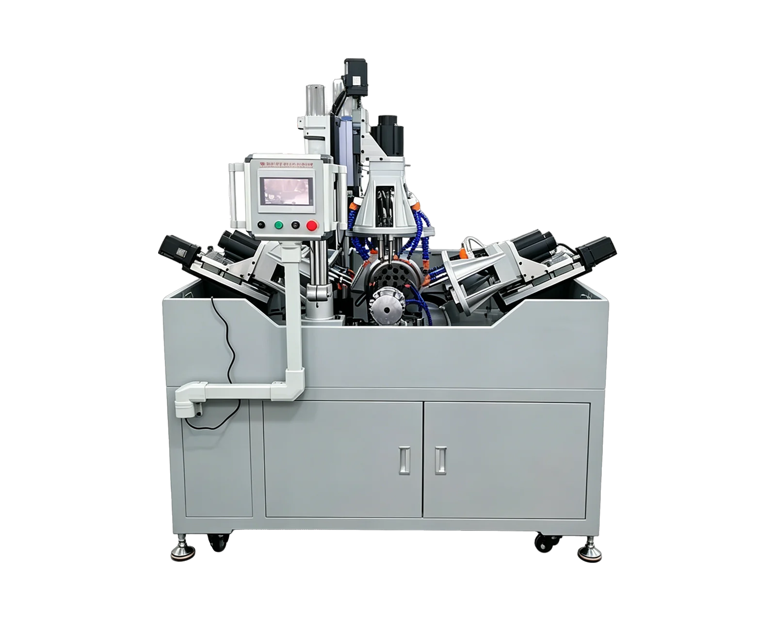
Explore equipment for your inquiry
Multi-Side Drilling & Tapping →Review the layout options and required part information to define the scope of a custom equipment inquiry.
1. Focus the inquiry on the individual support bracket
A roller support bracket inquiry should start with the bracket drawing rather than a complete conveyor or machine assembly. Identify the component, material and incoming manufacturing stage. Show whether the bracket is a formed part, a casting, a machined item or an assembly, and supply photographs of the actual condition available for a trial. The process review must be based on that supplied condition.
Locate the shaft-related feature and the mounting features on the drawing. Identify their entry faces and references without assuming they can all be produced in one operation. If the shaft is retained through a separately purchased item, provide the relevant interface information and identify the buyer-approved bracket definition. Keep the question focused on the bracket's specified features and the work required at the proposed station.
2. Assign the shaft feature its own process boundary
The word hole can conceal different requirements. A mounting clearance hole and a shaft-related feature may have different endpoints, inspection methods or later finishing owners. Ask the responsible designer to define those requirements on controlled documents. The equipment quotation should show the operations it covers rather than assume that drilling alone supplies every finished feature on the bracket.
3. Treat handed versions as separate evidence
List left and right bracket part numbers with a common orientation reference from the assembly. Then show each component in its own loading orientation. A mirrored outline may have a different retaining-thread direction, mounting pattern or accessible face. Highlight these differences so the supplier can assess which operations are shared and which need a separate arrangement or changeover review.
State whether production delivers brackets individually or as identified pairs. If pair-level records are required, define what links the two component records and what the pair check actually measures. Do not substitute a pair photograph for individual feature results. If the buyer expects an assembly trial with a shaft or roller, identify those supplied items and the questions the trial is intended to resolve.
4. Distinguish a prepared shaft feature from a finished one
Hypothetical purchasing example: a bracket arrives with a preliminary shaft opening, and the equipment inquiry covers its mounting holes and a retaining thread. A separate process will finish the shaft feature afterward. The proposal should identify that incoming opening and the later finishing boundary. Calling the bracket complete after the drilling trial would hide a remaining operation and could make two otherwise different quotations appear comparable.
If purchasing wants to bring the shaft-feature finishing into the same equipment project, request a revised scope assessment using the released feature requirements. Do not assume that the original drilling proposal includes the added work. Review the required samples, measurement responsibilities and handover condition again. Keep the original result tied to the original operation list so the evidence remains understandable when the project expands.
5. Compare proposals against component and pair requirements
Prepare a version list showing quantities, feature differences and incoming conditions. Ask the supplier to identify the covered brackets and the proposed sequence for features on different faces. Request clear exclusions for any finishing, assembly or inspection work that remains elsewhere. Where pair checks are requested, agree the sample identities and measurement condition before they become acceptance requirements.
Email BINSING the bracket drawings, operation map, left and right photographs and relevant shaft-interface references. Explain whether the objective is component production or a wider project that also includes a defined assembly stage. A clear response should connect the proposed drilling and tapping arrangement to specific bracket evidence. Roller alignment, running behavior and complete-machine performance require separately defined assembly requirements and verification by the responsible team.
