Explore equipment for your inquiry
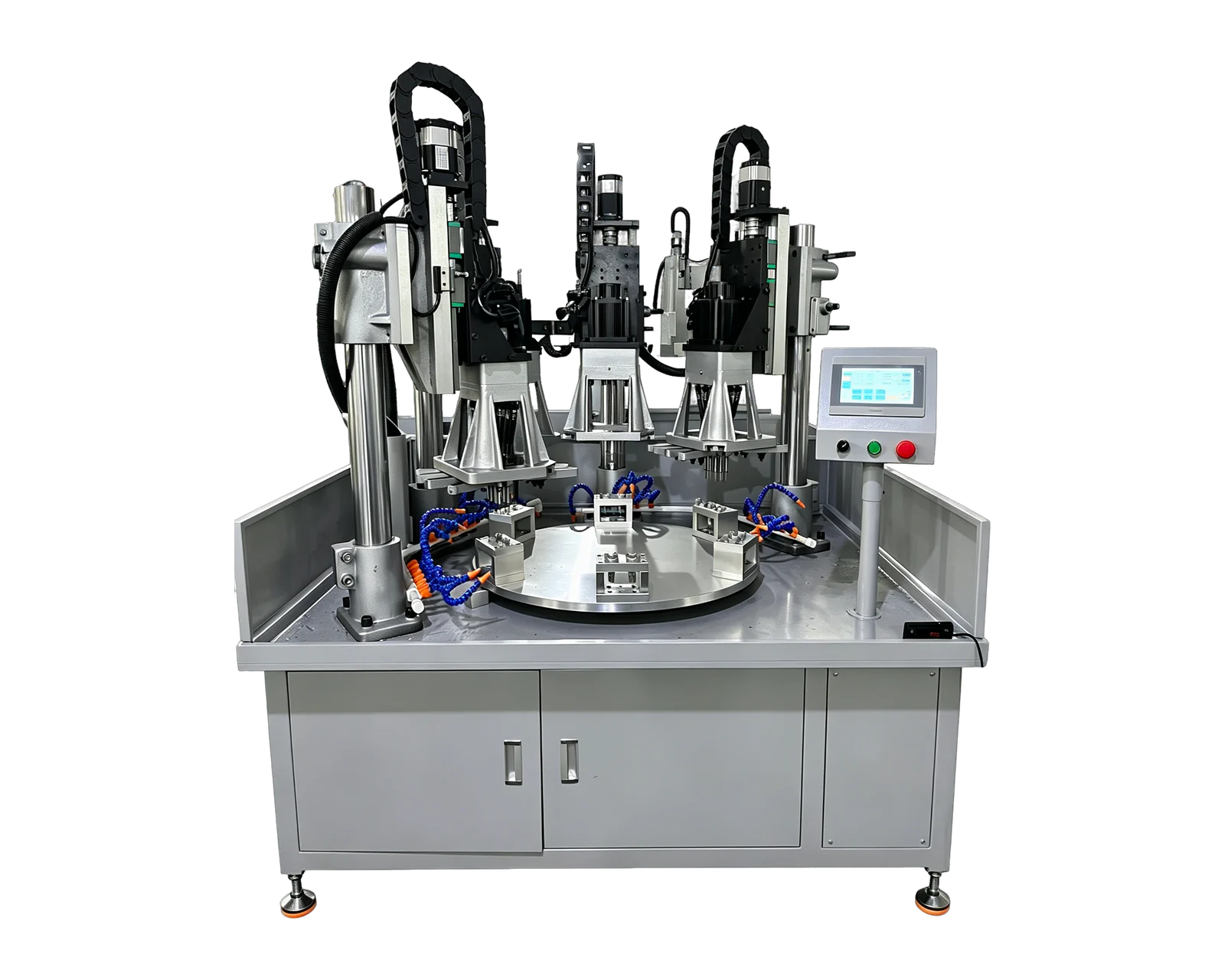
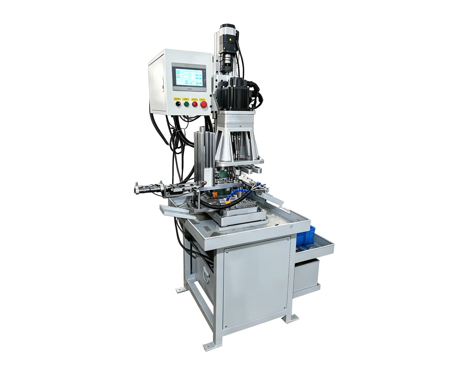
Automatic Feeding & Tapping →Review the layout options and required part information to define the scope of a custom equipment inquiry.
Describe the carrier as well as the component
A loose-part drawing does not describe the tray that will arrive at the machine. Supply the carrier drawing or measured reference information, its identifier, the pocket arrangement and the intended orientation of the whole carrier. Distinguish a transport tray from a carrier intended to remain with the workpiece during processing. That distinction changes the interface questions even when the component itself is unchanged.
Record whether one carrier design serves several component variants. Explain how its identity and contents will be communicated at the transfer boundary. Photographs are useful for showing the proposed arrangement, but they should supplement a controlled position map. Avoid assuming that a pocket number or orientation convention used upstream is already understood by the equipment supplier.
Give each position an unambiguous meaning
The illustrative register below describes information to agree rather than a supplied automation function. Use a marked view with an orientation reference so position names remain meaningful when the carrier is moved. State whether identification is provided by the buyer's system, an operator procedure or a separately agreed equipment function.
Include empty pockets and incomplete carriers
A tray shown completely full in a concept image leaves important production cases unresolved. State whether partial trays are permitted, how missing parts are identified and what information accompanies a carrier returned before completion. The design team needs the required outcomes for these cases. It should determine the corresponding equipment behavior through the project's normal engineering and safety review.
Consider a hypothetical tray with positions A through F where C arrives empty. The requirement should identify whether that carrier is acceptable, who knows C is empty and what record the receiving process expects afterward. This example establishes the information boundary; it does not prescribe sensors, handling motions or an operating procedure for an incomplete load.
Account for return flow and carrier condition
Specify whether incoming and outgoing parts share a tray or use different carriers. Identify the destination of an empty carrier and any handover needed before it can be reused. If carriers circulate through several processes, name the owner responsible for their condition and identification. A machining quotation should not silently inherit responsibility for the entire carrier circulation system.
Discuss the condition expected at each boundary, including any relevant cleanliness, damage or identification requirements established by the project team. Ask how a carrier that does not meet those requirements is reported and who resolves it. Do not assume that a proposed machine includes carrier cleaning, repair, storage or sorting merely because it accepts parts delivered on a tray.
Review representative carriers before confirming supply scope
Provide representative carrier records together with component drawings and the intended production mix. Identify any proposed tray that does not yet exist as a development item. The review should distinguish customer-supplied carriers, machine-supplied transfer elements and interfaces belonging to another integrator. Record document ownership and the evidence needed before each boundary is considered agreed.
For a BINSING inquiry, email a marked carrier view, pocket map, part drawings and a brief description of arrival and return responsibilities. Include partial-load cases and carrier variants. This lets the discussion focus on a defined transfer arrangement and helps keep unconfirmed carrier handling functions out of assumptions about a standard machine or custom solution.