Explore equipment for your inquiry
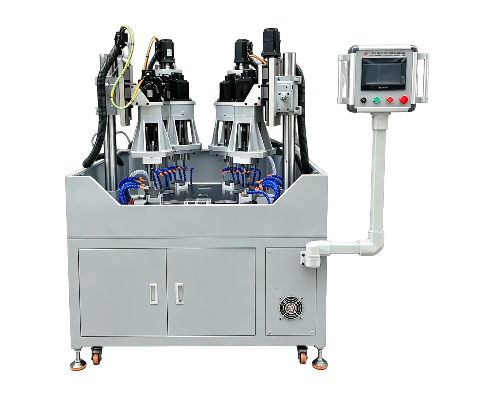
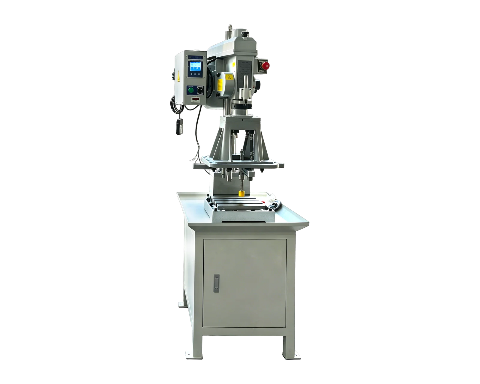
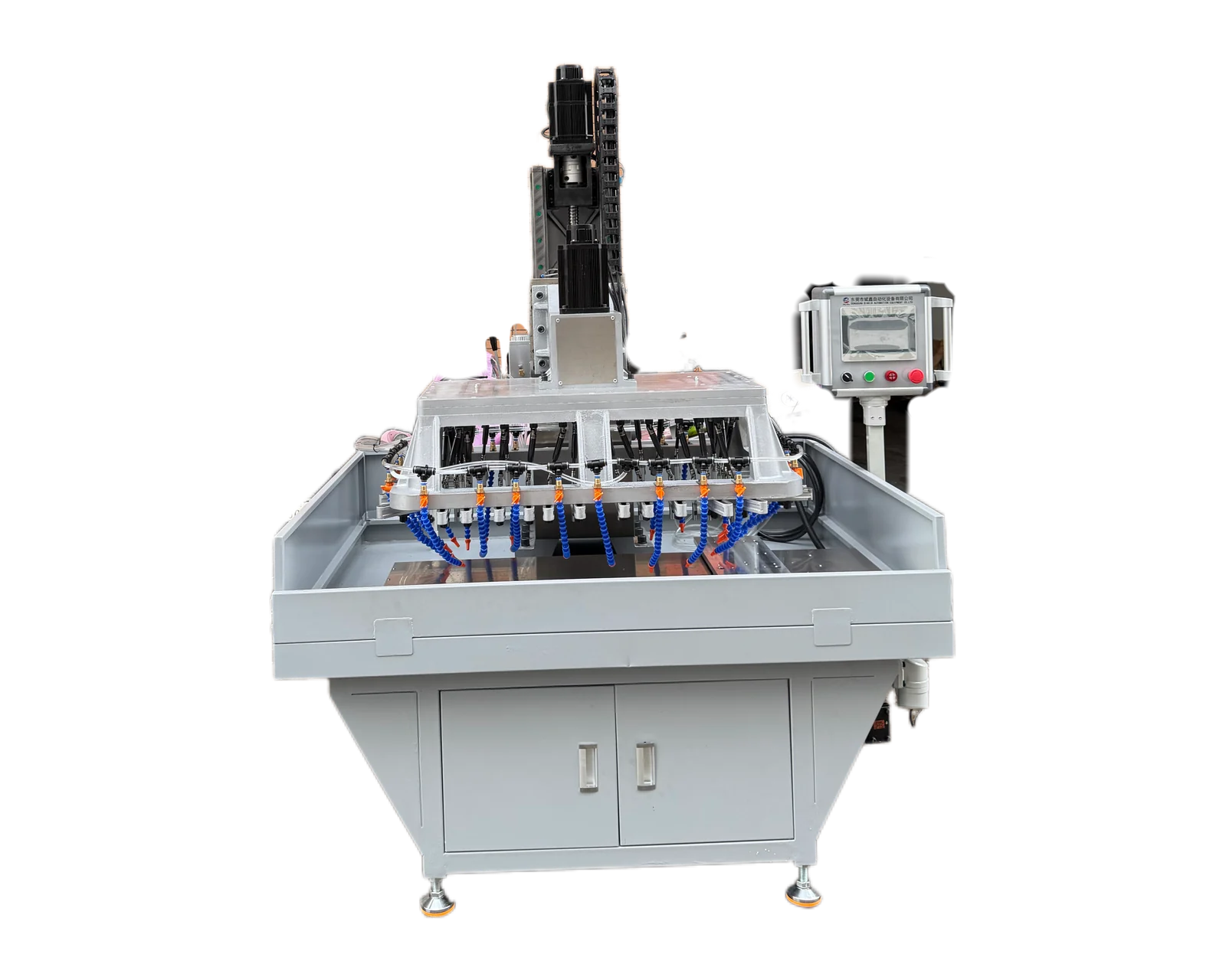
Dual-Servo Multi-Spindle Drilling & Tapping Machine →Review the published specifications and configuration options against your part drawing before requesting a quote.
Define the component, not just the assembled box
A terminal-box inquiry may refer to a cast body, a removable cover, an adapter or a mounting component. Identify which individual part enters the machine and whether internal equipment is absent at this stage. Provide its material designation and incoming shape. An assembly photograph helps explain orientation, but the machining proposal needs the component drawing and relevant sections.
Mark the motor interface and any controlled mating surfaces. Show which faces already exist in their accepted condition and which require an earlier operation. If two terminal-box variants share an exterior but use different mounting or entry arrangements, give them separate feature maps. This avoids treating an assembly option as an interchangeable machining program without checking its physical differences.
Classify holes by the interface they serve
Separate cover screws from motor mounting features and cable-entry connections. Supply the specified thread or hole requirement and its reference dimensions for each group. Where a purchased fitting is involved, attach its approved interface information rather than asking the machine supplier to infer the connection from a sample nut or an approximate outside diameter.
Use the same identifiers in the drawing, quotation and inspection plan. A hole count alone can conceal different approaches, depths and finishing operations. State whether entry preparation, tapping, edge finishing and cleaning belong to this purchase. If a feature needs a process beyond the proposed drilling or tapping scope, keep it as a separate operation with an identified owner.
Use a terminal-box feature and responsibility map
This original template turns the assembly into a machining inquiry. Fill only the rows present on your component and attach the controlled requirements. It does not define electrical clearances, sealing requirements or a protection rating.
Set the coating stage and chip-removal handoff
State whether machining occurs before or after painting or another specified finish. Hammond's enclosure modification page describes producing holes and cutouts before painting as part of its own manufacturing route. That is a useful example of why operation order belongs in an inquiry, not a universal rule for every motor terminal box or a claim about BINSING's finishing services.
For the proposed route, identify protected contact surfaces, the accepted condition of newly machined edges and who performs any approved finish restoration. Define the cleanliness handoff before downstream assembly, including features where chips may remain out of direct view. Record the inspection method and owner rather than assuming that unloading the component completes every cleaning requirement.
Keep machining evidence separate from assembled-product evidence
A hypothetical trial may show that mounting holes and cover threads meet their component drawing. It does not establish the performance of the assembled box, installed entries, gasket or electrical equipment. Ask the product owner to identify the required assembly checks and any applicable qualification route. Do not describe a machining trial as an enclosure-rating or electrical-certification test.
Send BINSING the component drawing, interface references, coating-stage description and production mix. Request an application-specific review of access, workholding and the included drilling and tapping operations. If left- and right-entry versions are required, include both in the variant list and ask how identification, setup and first-piece inspection will distinguish them before production quantities are priced.