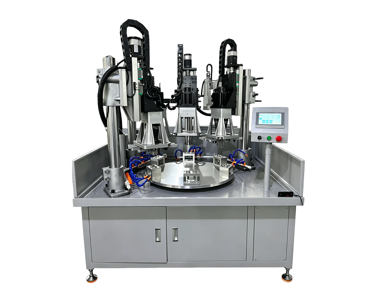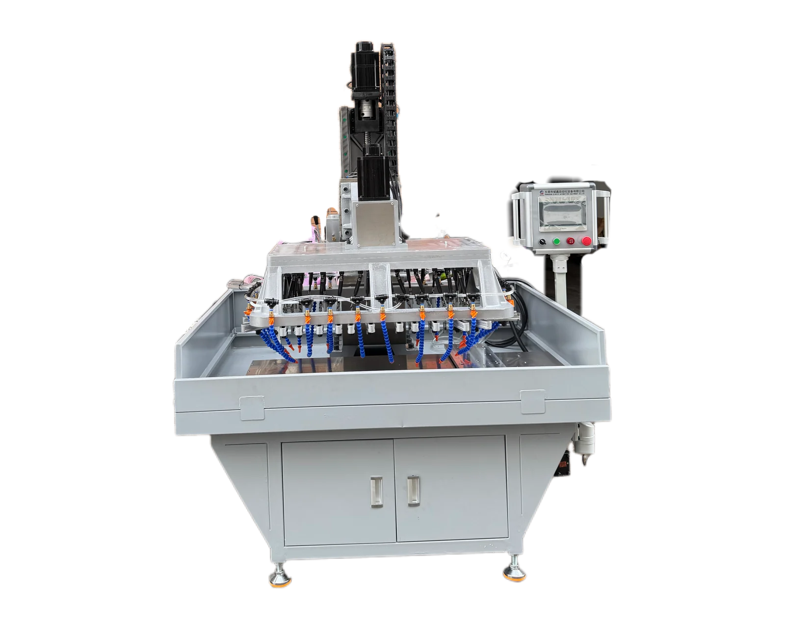
Explore equipment for your inquiry
Servo Traverse Multi-Spindle Drilling & Tapping Machine →Review the published specifications and configuration options against your part drawing before requesting a quote.
Start with the visible configuration
The linked BINSING reference video shows a servo-traverse multi-spindle machine. Reviewed source frames show the control panel, a row of tooling positions, coolant hoses and a dedicated workholding area. These are useful subjects for a layout discussion. They do not provide a readable workpiece drawing, a verified coordinate list or a measurement report for the machined features.
When sharing the video with your purchasing and process teams, attach a marked view of your own part. Explain whether the interest is access to several locations, reuse of a tooling group or accommodation of a part family. A request that simply says same as the video leaves those different requirements unresolved and can lead to quotations with different fixture and tooling assumptions.
Keep machine positions separate from drawing features
A feature identifier belongs to the part drawing; a position identifier belongs to the proposed machine sequence. They should be connected, but they are not interchangeable. One tooling group might address several drawing features in a proposed sequence, while a single feature might require more than one operation. Record the intended relationship before comparing platform sizes or discussing program changes.
For a hypothetical part family, label features F1 through F4 and proposed positions P1 and P2. These labels are an inquiry example, not a reconstruction of the filmed machine. Ask the supplier which feature-operation pairs are assigned at each position, which references locate the part and what must change for another variant. Keep actual coordinates and tolerances in the controlled drawing package.
Use a position review sheet with explicit open items
The original worksheet below turns the selection-stage position map into an evidence request. Add a row for every feature-operation pair, with the drawing revision in the header. Record a time reference only where the relevant step is actually visible. Mark obscured movements and off-camera operations as unverified instead of reconstructing them from the final machine position.
Review the fixture through every proposed position
The workholding discussion should follow the complete proposed sequence. Ask how the part is located, how loading orientation is controlled and which clamps or supports influence access. A clear photograph of the open fixture is useful, but it cannot replace a review with the actual part envelope and tooling arrangement. Identify where the operator needs access for loading, cleaning and changeover.
Keep fixture changes distinct from coordinate changes. A part variant can share nominal hole spacing while differing in an external surface used for locating, or share an outline while requiring different feature relationships. Mark those differences individually. The inquiry should let the supplier explain whether the proposed fixture can be retained, modified or exchanged, without assuming that a program edit covers every variant.
Request evidence that follows your feature map
For a subsequent application demonstration, ask for the part identity and drawing revision to be recorded with the proposed sequence. Request enough views to connect the workholding arrangement and tooling groups to the worksheet. Where a movement or processing step is obscured, request a supplementary view or a sequence explanation rather than inferring its purpose from camera motion.
Close the review with identified sample parts and agreed dimensional checks. Keep the machine demonstration, the sequence description and the inspection results as separate but linked records. For a BINSING inquiry, send the drawings, material condition, variant list and quantity with the position worksheet. This gives the equipment discussion a concrete starting point while leaving application-specific travel, tooling and acceptance requirements to the proposal.