
Machine selection · Standard machines

When to Use a Servo-Traverse Drilling and Tapping Machine

Choose a servo-traverse drilling and tapping layout by mapping feature groups to positions, then reviewing movement, tooling, fixture access and changeovers.

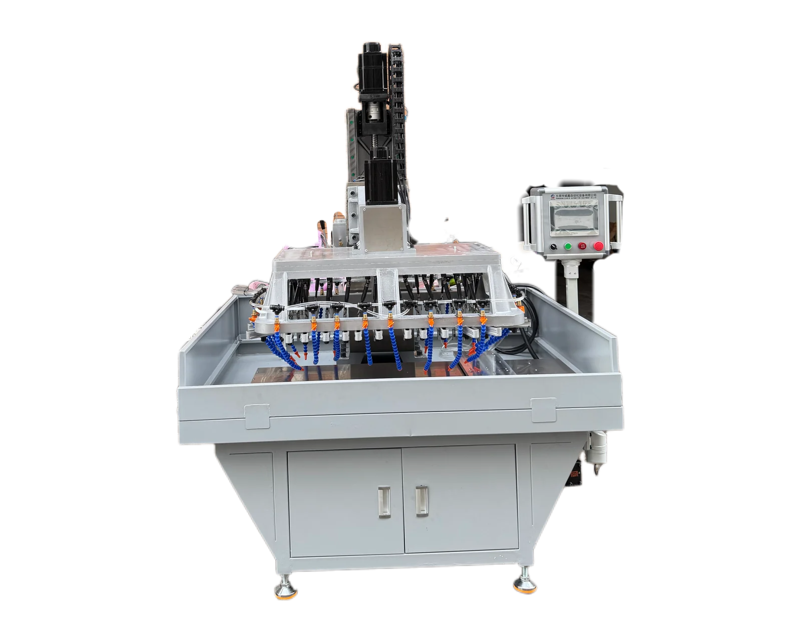
Servo-traverse multi-spindle drilling and tapping platform

The short answer

Consider a servo-traverse drilling and tapping machine when the required feature groups or operations need more than one reviewed machining position. First identify what must move, which tool group works at each position and how the part remains located. Compare that sequence with a fixed multi-spindle arrangement or rotary layout before selecting the platform. Servo motion alone does not confirm travel, tool access, one-clamping completion or coverage of every variant.

Explore equipment for your inquiry

Servo Traverse Multi-Spindle Drilling & Tapping Machine →

Review the published specifications and configuration options against your part drawing before requesting a quote.

Start with the reason another position is needed

Mark the groups of holes and the required operations on the drawing. Explain why one machining position may be insufficient: separate feature groups, a drilling-and-tapping sequence or another defined positioning requirement. The objective is to describe the finished part and workflow before selecting a movement arrangement.

Ask the supplier to show what moves in the proposed configuration, where the workpiece is held and which tools act at each position. The catalog describes a servo-traverse multi-spindle platform; the actual traverse sequence and tooling are selected for the application. Avoid inferring the complete machine sequence from the product name.

Create a position-by-position process map

A simple map helps expose missing operations and access questions. It need not prescribe the final machine design. Its purpose is to give the supplier a clear account of the required work and make competing proposals easier to compare.

Information to define for each proposed position
Process-map fieldWhat to provideWhat to confirm
Feature groupHole identifiers from the drawingWhich features the position completes
OperationDrilling, chamfering, tapping or other required workIncluded tooling and operation order
Position referenceDimensions from part reference surfacesTravel and positioning arrangement
WorkholdingAccessible clamping and locating areasClearance through the whole movement
TransitionPart condition before the next operationTool retraction, movement and any intermediate handling

Review the entire movement envelope

Provide the full part dimensions, including projections that are away from the holes. The layout review should consider the fixture and workpiece at every proposed machining and loading position. Ask how tools, clamps and nearby machine components are accommodated throughout that sequence.

Include the intended method for loading and removing the part. A process can appear clear in a machining diagram while still leaving an awkward handling step. Explain operator access, available space and any planned connection to upstream or downstream equipment so those interfaces can be addressed in the proposal.

Describe part-family changes explicitly

List what changes between versions: overall length, hole spacing, material, thread specification or machining faces. Request a changeover description for representative variants. Distinguish adjustments to the position sequence from changes to tooling, head layout or workholding; these should not be treated as interchangeable.

If the production mix is still uncertain, say so. Ask the supplier to state the parts and variations covered by the quotation and the assumptions used for the proposal. This is more useful than a broad promise of flexibility that does not identify which future changes the machine can accommodate.

Compare a complete sequence with alternative layouts

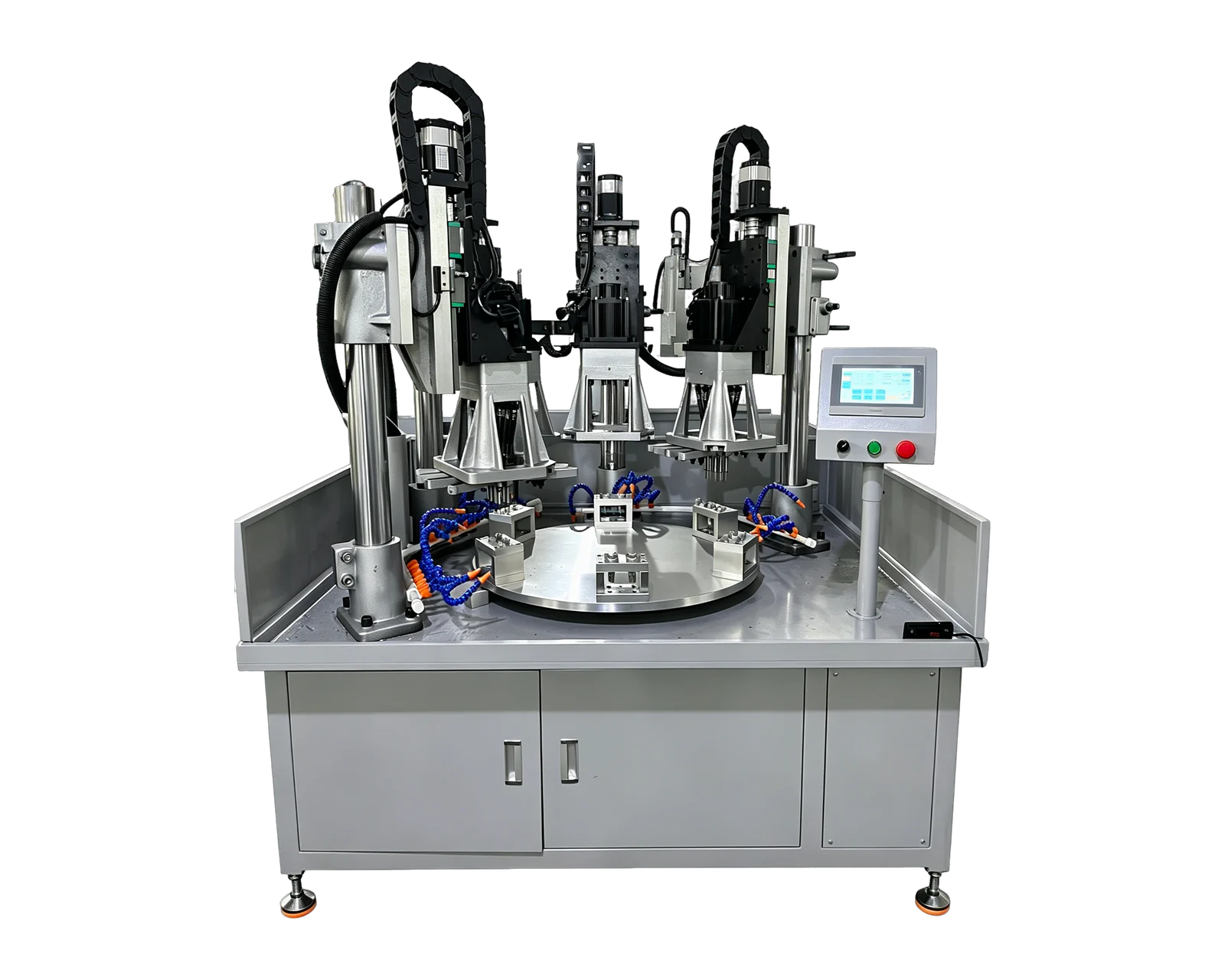
A fixed multi-spindle platform may be sufficient when the required features are accessible in one arrangement. Rotary indexing may deserve review when parts pass through distinct stations. Multi-side machining may be relevant when the feature directions, rather than traverse positions, drive the process. None of these options should be selected from the title alone.

For the traverse proposal, confirm the machining scope, total handling sequence and agreed inspection requirements. Ask for output estimates to state their part, tooling and loading assumptions. The existing video illustrates a configuration; use the separate video-review worksheet to request drawing-linked evidence after defining the candidate layout.
Which requirement makes a layout worth reviewing?
Drawing or production needCandidate to compareQuestion that decides the scope
One accessible repeated hole groupFixed multi-spindle arrangementCan the required features be reached without another position?
Several feature groups or tool positionsServo-traverse layoutWhat moves and which feature-operation pairs are covered at each position?
Parts passing through separate operationsRotary indexing layoutWhat happens at each station, including loading and discharge?
Long part or broad processing areaCustom multi-spindle or gantry layoutHow are full feature coverage, supports and loading access provided?

Prepare your part information

  • Complete drawing with feature groups and reference dimensions
  • Required operation sequence and any off-machine work
  • Material, hole and thread specifications
  • Part variants with changeover frequency
  • Loading method, available space and output target
Request a traverse layout assessment →

Common questions

Does servo traverse mean every hole position is programmable without tooling changes?

Do not assume this. The proposed movement, head layout and fixture must be reviewed together. Ask which changes use settings and which require physical components or adjustments.

Can drilling and tapping be included in one process?

The catalog platform supports drilling and tapping applications. Confirm the tools, positions and sequence needed for your drawing, including how the part moves between operations.

How much travel is available?

Travel is application-dependent in this catalog. Provide overall dimensions and required positions so the offered arrangement can state the necessary traverse and machining travel.

Related equipment and project information

Map the sequence for your part

Send the drawing with feature groups, operations, part variants and loading limits so BINSING can review positions, tooling and fixture scope together.

Request a traverse layout assessment ↗

Machine operation

Watch related equipment videos

Use these equipment examples to review the layout and operation. Tooling, workholding and the machining sequence must be agreed for your part.

Servo Traverse Multi-Spindle Drilling & Tapping Machine
STANDARD MACHINE / VIDEO

Servo Traverse Multi-Spindle Drilling & Tapping Machine

A servo traverse platform for positioning a workpiece through a multi-spindle machining sequence. Define the movement and tooling from your drawing.

View machine platform →