

Standard platform · BX-20015
Dual-Servo Multi-Spindle Drilling & Tapping Machine
Servo-controlled spindle rotation and feed on a multi-spindle platform. Match the head and fixture to the holes and threads in your part.
View machineStandard machines & custom configurations
Compare automatic drilling and tapping machines for repeated metal parts. Choose a starting layout from the holes, threads, machining faces and operation order: a dual-servo platform, servo traverse, rotary indexing or a custom multi-side or gantry configuration. Define the complete route before comparing equipment prices.
Choose a starting platform
Start with the machining task, then review the platform specifications and the tooling your part needs.
| Platform | Application fit | Catalog reference |
|---|---|---|
| Dual-Servo Drilling & Tapping | Parts with repeated hole or thread patterns that benefit from coordinated multi-spindle machining. | Drilling range: Ø1–15 mm Tapping range: M0.8–M16 Spindle travel: 50–200 mm |
| Servo Traverse Drilling & Tapping | Repeated hole layouts or machining sequences requiring controlled traverse positioning. | Platform: Servo traverse, multi-spindle Spindle arrangement: Selected from the hole pattern Traverse and machining travel: Confirmed from the part dimensions |
Catalog ranges describe each platform, not guaranteed results for every material or spindle arrangement. Confirm the selected tools, fixture and process with your drawing. Scroll the comparison table horizontally on smaller screens.
Standard platform · BX-20015
Servo-controlled spindle rotation and feed on a multi-spindle platform. Match the head and fixture to the holes and threads in your part.
View machine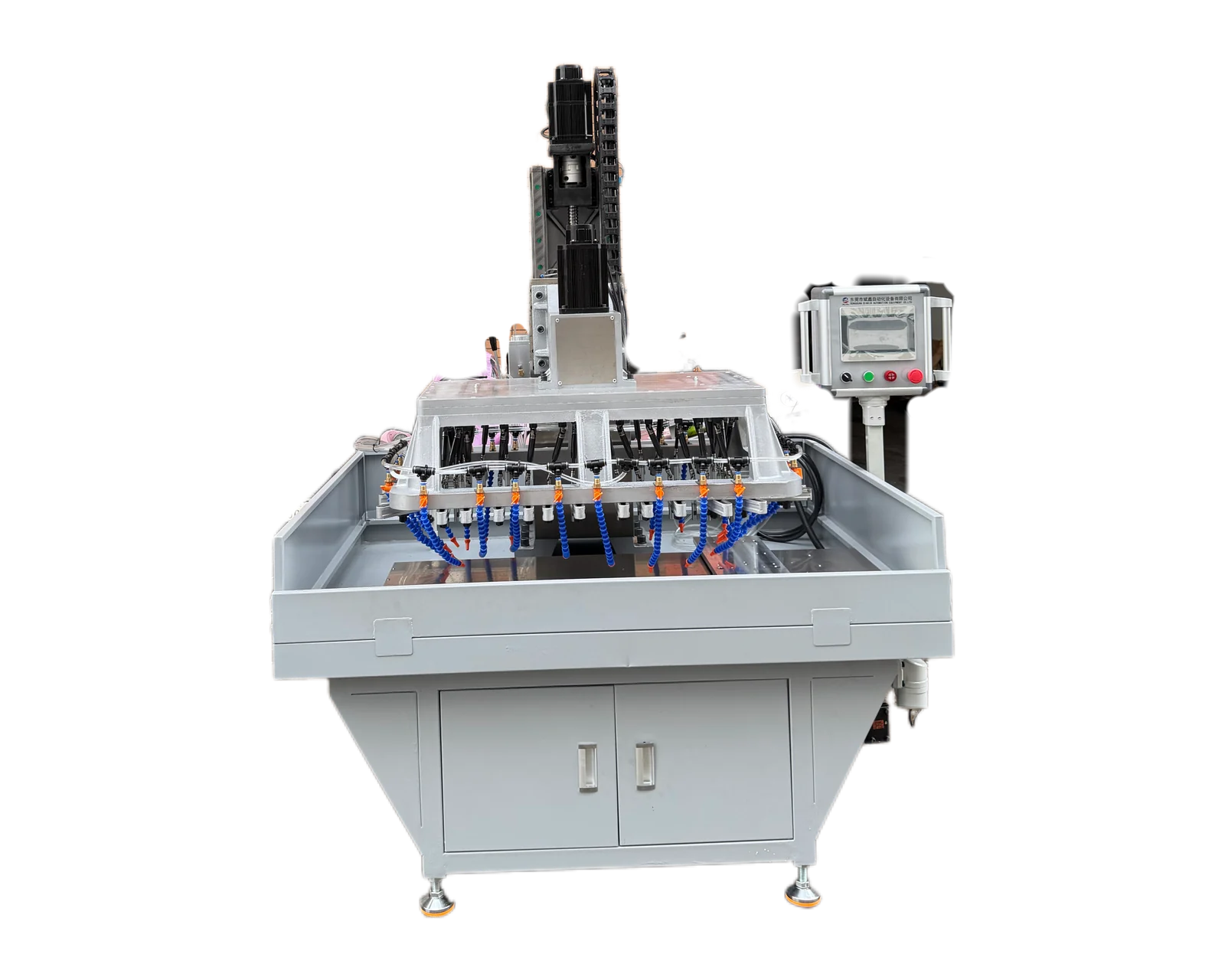
Standard platform
A servo traverse platform for positioning a workpiece through a multi-spindle machining sequence. Define the movement and tooling from your drawing.
View machineApplication review
Start with the required operations and accessible faces. These are routes to assess against your drawing, not promises that every listed operation is included in a standard machine.
| Your requirement | What to review | Explore the options |
|---|---|---|
| A defined hole or thread pattern | Review the matched head, tools and fixture. Identify how drilling and tapping are selected or sequenced in the actual offer. | BX-20015 dual-servo platform |
| Several machining positions | Map feature groups to traverse positions and confirm what moves, what stays clamped and where tooling changes occur. | Servo-traverse platform |
| Successive operations around indexed stations | Assign drilling, edge preparation, tapping and loading to named stations, with the part state after each step. | Rotary indexing layout |
| Features approached from different faces | Review tool directions, support and clamp access together; distinguish face access from the number of controlled axes. | Multi-side machining layout |
| A dedicated worktable or larger hole pattern | Provide the complete workpiece and fixture envelope so the head layout, usable area and loading interfaces can be defined. | Custom multi-spindle and gantry layout |
Scroll horizontally to compare all columns on smaller screens.
Define what is automatic
Describe the incoming blank, drilling, any required edge preparation, tapping and finished-part destination. At each stage, identify the working tool, part location and operator task. A platform with drilling and tapping capability does not by itself include automatic tool changes, part loading or a complete cycle in one clamping. Confirm each action in the offered configuration.
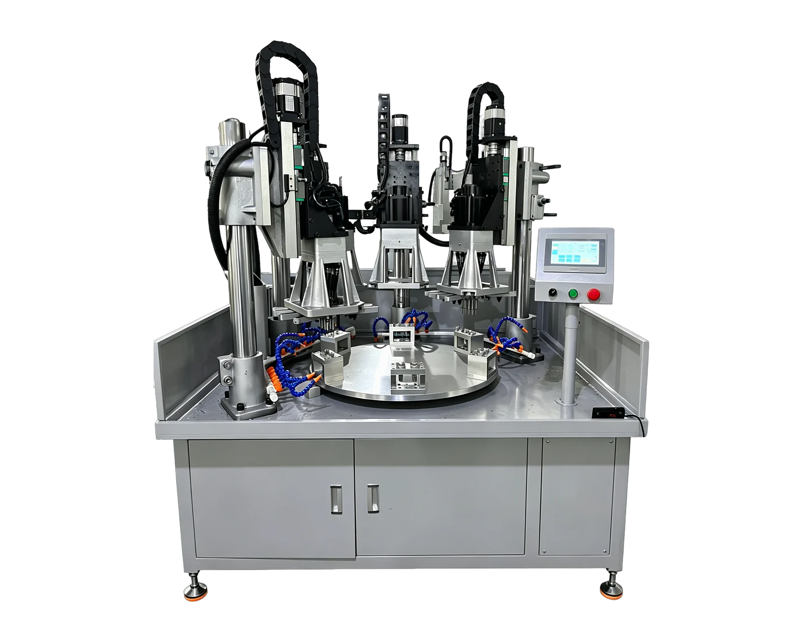
Custom solution
Move parts between drilling, chamfering and tapping stations on a rotary layout. Station count, tooling and loading are designed around the workpiece.
View solution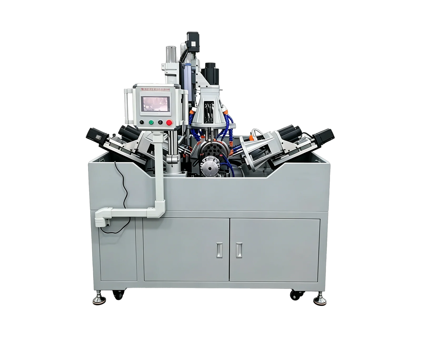
Custom solution
Combine vertical and horizontal machining heads for parts with holes or threads on multiple faces. Confirm access, clamping and the operation sequence before selecting a layout.
View solution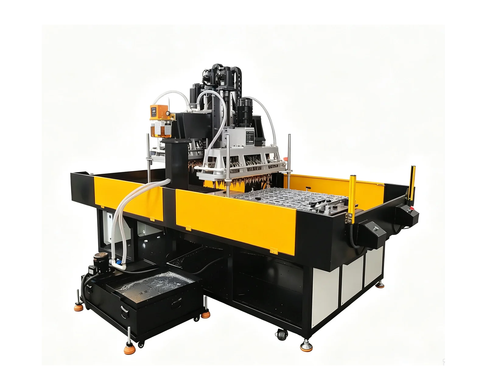
Custom solution
Custom multi-spindle and gantry arrangements for workpieces requiring a dedicated hole layout, worktable or fixture. Machine dimensions and cutting conditions follow the actual part.
View solutionMachine operation
Use these equipment examples to review the layout and operation. Tooling, workholding and the machining sequence must be agreed for your part.
Servo-controlled spindle rotation and feed on a multi-spindle platform. Match the head and fixture to the holes and threads in your part.
View machine platform →Price & quotation
An automatic drilling and tapping machine quotation should cover the same finished work as the alternative route. Identify the heads or stations, tools and holders, fixtures, positioning, loading and agreed trial. List chamfering, cleaning and inspection as included or separately supplied. Use that scope to compare a combined system with separate machines; the base-machine price alone cannot establish the cost of the completed route.
Understand machine cost factors →That depends on the selected tooling, positioning and fixture arrangement. A platform listed for drilling and tapping is not by itself a promise of an automatic combined sequence. Provide the drawing and required operations so the proposal can define each tool, machining position and handling step.
Compare the same incoming blank and finished part, including transfer, intermediate cleaning or inspection, operator work and changeovers. A combined arrangement may reduce transfers, while separate stations may serve different jobs independently. Ask for a complete sequence for each proposal before comparing accepted output or investment.
Include the specified edges and their finished requirements on the drawing. The supplier must identify the tools, access and sequence used for those edges, plus any work left outside the machine. Drilling and tapping capability does not establish a chamfering or deburring scope.
A rotary layout can move parts between successive machining stations. A multi-side layout provides tool access from different directions. Review these options when the operation sequence or machining faces require more than the proposed standard setup, with clamping, transfer and loading defined together.
Send the complete part drawing, material, drilled-hole dimensions, thread specifications and any chamfer requirements. Add the current process, part variants, target output and preferred loading method. These details allow the proposal to distinguish machining time from loading, transfer and other cycle stages.
Share a drawing or photo, the required operations and your output target. You can begin without choosing a machine.