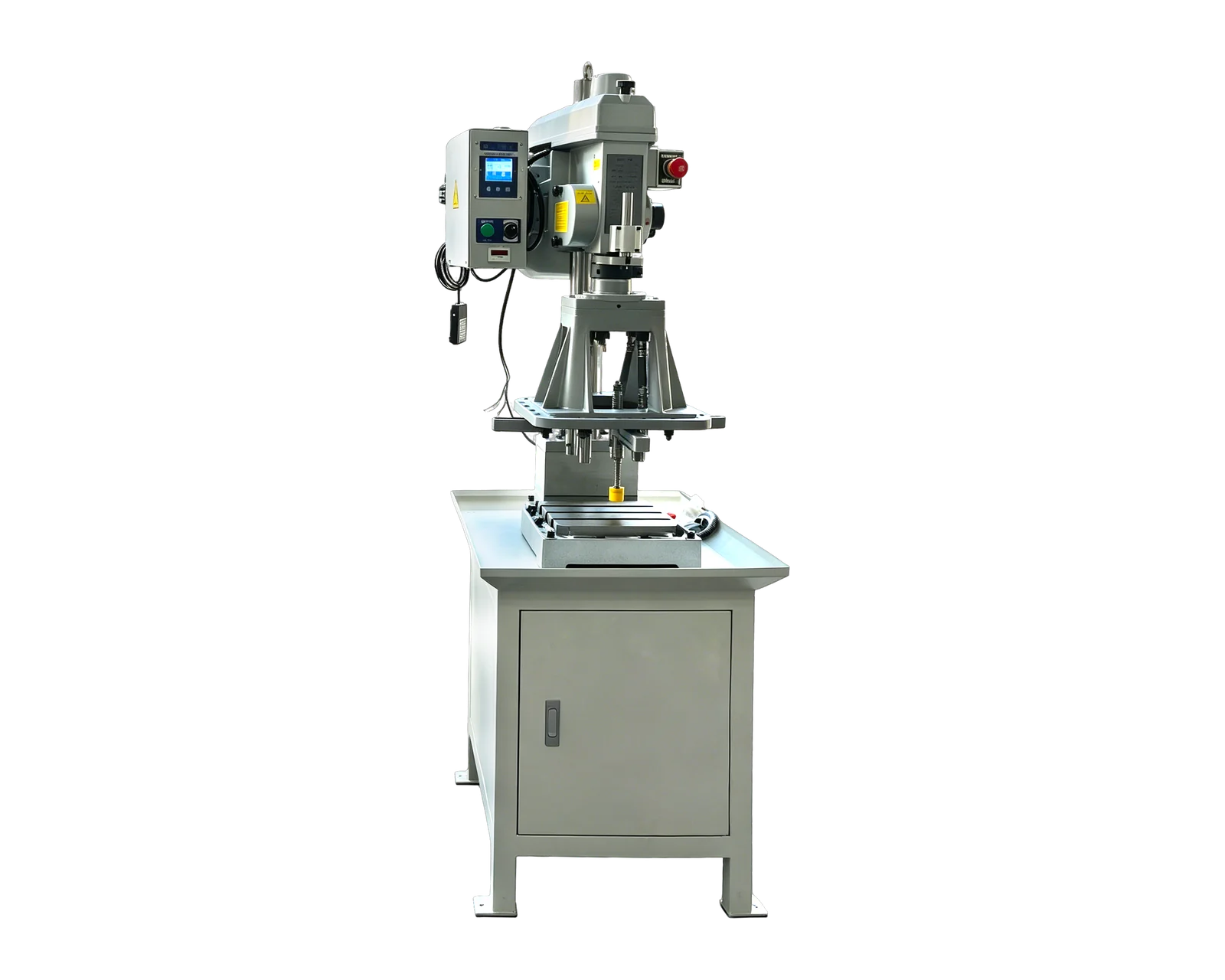
Workholding through the route
Map tool access and clamping for each feature. Identify whether the part stays in one fixture or is transferred, and how drawing relationships will be inspected after the complete sequence.
Custom solution
Plan drilling, chamfering and tapping around a rotary indexing table. BINSING reviews the station assignments, fixtures, tooling and loading method against your part drawing and process route. Request a multi-station configuration with a clearly defined scope.
Define your configuration
This illustrative route explains the questions a station plan should answer. It is not a specified station count or a claim that every listed operation is supplied. A proposal may combine, separate or omit functions after reviewing the part.
| Function | Scope to review | Confirm for your part |
|---|---|---|
| Load and locate | Part enters in the agreed supplied state and is located for the route. | Who loads it, how orientation is established and which references locate it |
| Drill | Required starting hole is produced before its downstream thread operation. | Feature IDs, tool access, chip clearance and prepared-hole requirements |
| Chamfer, if required | The drawing-defined edge or entry is prepared at its assigned stage. | Which face is reached and whether a separate position or tool is needed |
| Tap | Prepared hole reaches the assigned tapping tool. | Thread specification, depth, feed/rotation relationship and withdrawal method |
| Unload and verify | Completed part leaves the route; agreed checks establish disposition. | Which checks are included, which occur outside the machine and where parts are collected |
Scroll horizontally to compare all columns on smaller screens.
Several parts may occupy different positions at the same time in a reviewed layout. One part still follows its required operation order. Station count, machining-head count and finished parts per index are separate quantities; none alone establishes output.
Map tool access and clamping for each feature. Identify whether the part stays in one fixture or is transferred, and how drawing relationships will be inspected after the complete sequence.
Request a timing diagram that identifies machining, tool withdrawal, indexing, settling and loading/unloading. Confirm which actions can overlap. Compare accepted parts over the agreed observation period, including relevant interruptions.
Compare both against the same part variants, required operations and incoming state. The movement label alone does not settle tool access, changeover work or output; request a complete route for each candidate.
Equipment examples
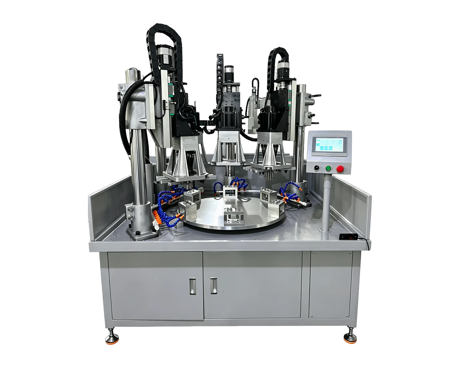
These real equipment references illustrate different layouts. Specifications and performance are confirmed for the proposed configuration and workpiece.
Custom equipment reference
Separate stations carry out successive operations on an indexed part.
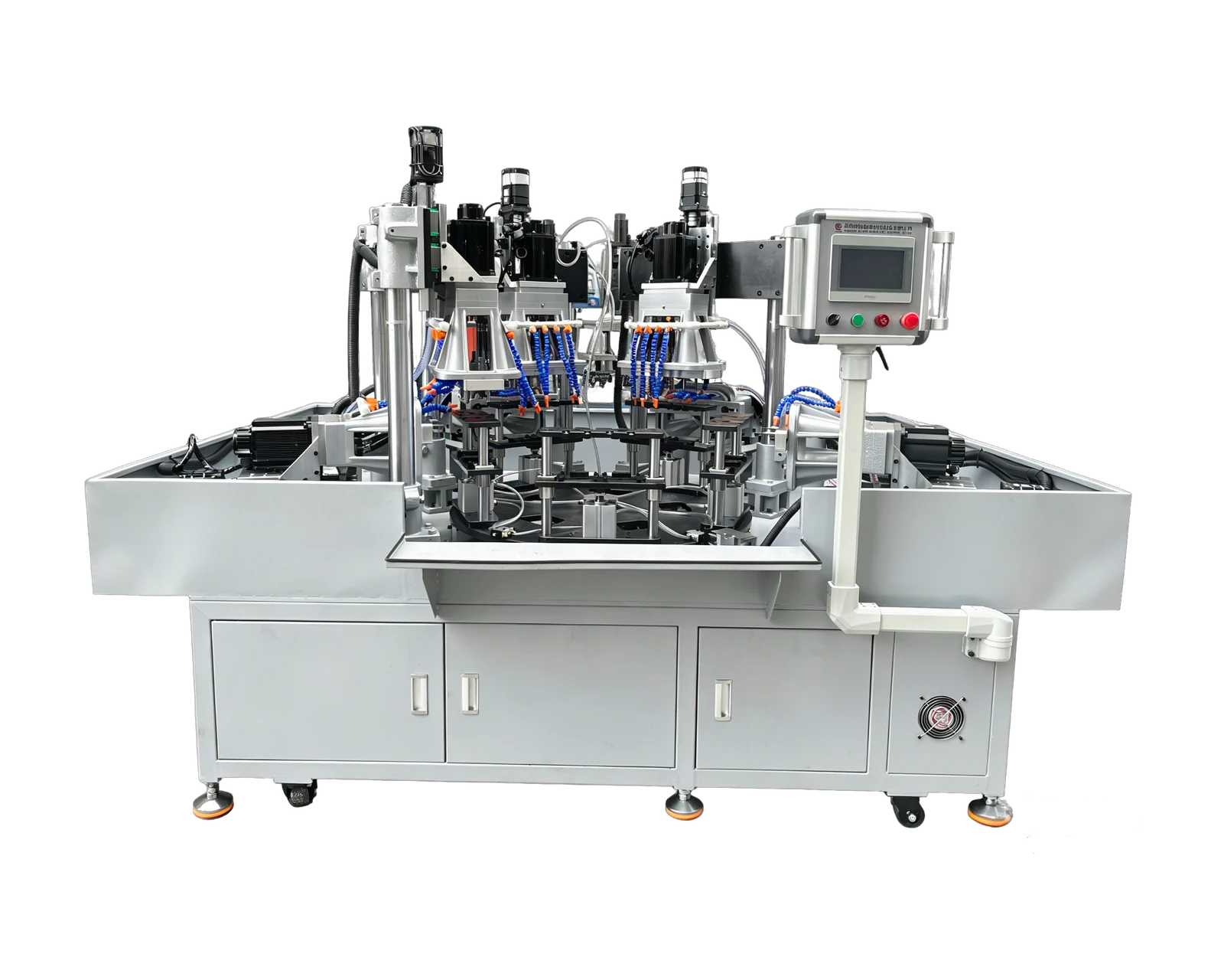
Custom equipment reference
A rotary layout brings multiple machining heads into one part-processing sequence.
Machine operation
Use these equipment examples to review the layout and operation. Tooling, workholding and the machining sequence must be agreed for your part.
Move parts between drilling, chamfering and tapping stations on a rotary layout. Station count, tooling and loading are designed around the workpiece.
View related solution →Price & quotation
A rotary drilling and tapping machine quotation should identify the indexing arrangement, station functions, installed heads, fixtures, tooling and loading scope. Add controls, chip/coolant handling, discharge and agreed inspection separately. Distinguish the supplied configuration from optional future stations or functions.
Before ordering
The layout must define which stations work together and which actions wait. Drilling and tapping the same hole remain ordered operations, even if other parts are being machined elsewhere during the same interval.
Start with the required operations, access, workholding and handling functions. The reviewed route determines the station arrangement. A published machine image is a configuration reference, not a fixed station specification for your part.
Manual or automatic loading can be reviewed with the rotary layout. Automatic feeding needs its own part-presentation assessment and scope. Include incoming packaging, orientation, protected surfaces and representative parts in that review.
Continue your review
Assign a clear responsibility to each stage.
Compare layouts over the same process boundary.
Link the visible layout to the evidence you need.
Keep the handling scope visible in the offer.
Also consider
If a defined platform suits the part, compare these standard machines before specifying a complete custom arrangement.
BX-4508V
Repeated tapping operations where thread size, pitch and workholding can be defined in advance.
View machineBX-20015
Parts with repeated hole or thread patterns that benefit from coordinated multi-spindle machining.
View machine