
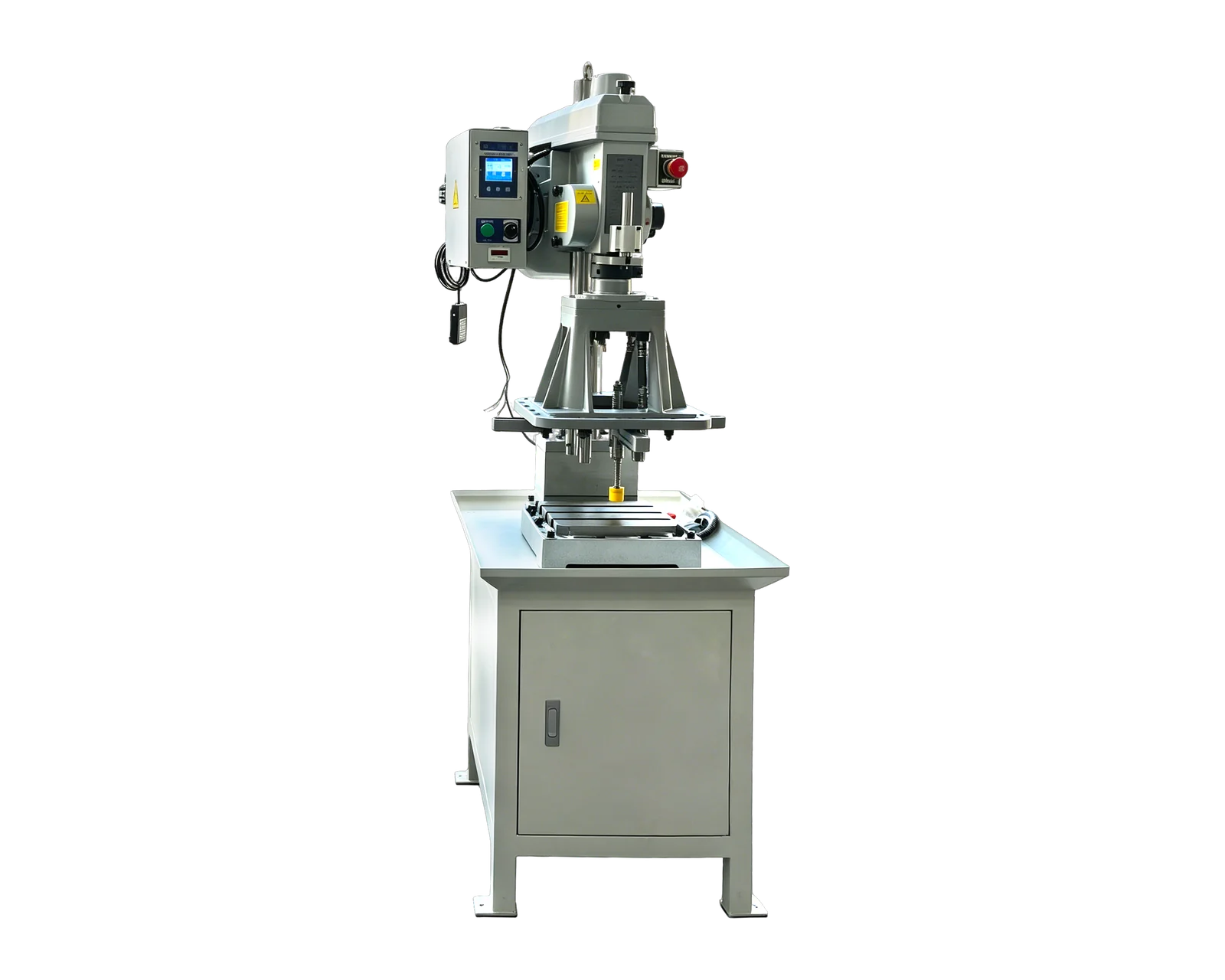
Explore equipment for your inquiry
4508 Gear-Driven Automatic Tapping Machine →Review the published specifications and configuration options against your part drawing before requesting a quote.
Read the direction relative to the tool, not gravity
OSG groups spiral-flute taps with blind-hole applications and spiral-point taps with through-hole applications for materials producing coiled chips. These are starting categories, not approval of a particular tool. The important distinction for a layout review is where the selected cutting geometry intends to send the chips.
VÖLKEL describes forward chip transport for the spiral-point version of its HexDrive tools. OSG's chip-shape guidance describes spiral-flute discharge opposite to the tool feed. The original direction map below translates those two principles into a section-view annotation. It describes ordinary intended flow, not a guarantee that every chip follows the arrow.
- Tool feed: entry face → cutting zone → far side or closed bottom.
- Spiral point: cutting zone → ahead of the tool → available far-side collection space.
- Spiral flute: cutting zone → back along the flutes → entry-side collection space.
- For a horizontal spindle, keep the same entry/far-side labels. Up and down would describe the installation, not the cutting geometry.
A through hole can still have a blocked exit
Imagine a hypothetical thin bracket with a fully drilled through hole. On the drawing, the far side is open. In the proposed fixture, a solid support sits immediately behind it. Calling the feature a through hole has not established room for the tool or the intended chip discharge. This is a fixture-interface question to resolve before choosing the tapping arrangement.
Ask the layout reviewer to mark the complete installed path, including supports, nearby walls and any part beneath the feature. If a support must change, its locating and clamping role needs review as well. Do not simply remove support or assume that switching tap style makes the original fixture acceptable. Compare the proposed tool and fixture together.
Use material suitability as a separate filter
The two names do not divide every tapping application between them. OSG's product overview also lists other tap families for different chip behavior. Send the exact material designation and condition with the hole information. A tool listed for one alloy or chip behavior should not be selected for another solely because both parts have through holes.
Keep the manufacturer's full tool reference in the proposed route. A shop description such as spiral tap can conceal differences between products. Ask which specific application guidance supports the choice, and whether a material change would require a separate review. This makes substitution decisions more precise than assuming all tools with visibly similar flutes are equivalent.
Confirm discharge without turning the trial into a speed contest
OSG notes that poorly formed chips can become trapped between the tool and the machined thread. Its examples show why a nominal discharge direction alone is insufficient. Use the tool supplier's application guidance for operating conditions; this comparison does not prescribe speeds, feeds or a universal depth limit.
For the equipment evaluation, distinguish three observations: chips leaving the feature, chips reaching the collection area, and the condition of the part handed onward. Agree which observations need recording and inspect only through the planned safe access arrangements. A thread can meet its dimensional check while the surrounding layout still needs attention before repeated unattended cycles are considered.
For example, a hypothetical trial may show acceptable threads but require an extra stop to clear the entry area. Record that intervention as part of the tested arrangement. The purchasing question becomes whether the proposed collection method can support the intended operating pattern, rather than whether the first hole looked successful. No unattended-output claim follows from a short demonstration.
Ask for a tool-and-layout decision
A useful inquiry result is an annotated section identifying the candidate tap, intended discharge side, surrounding fixture and unresolved access questions. Request alternatives only where there is a concrete decision to make, such as modifying a backing support versus reviewing another tooling route. Keep their implications visible in the equipment comparison.
Send BINSING a section view and a photo of the part in its current fixture, if available. Mark where material can leave the machining zone and where it must not accumulate. This helps frame an application review; it does not establish that the pictured machine includes a particular chip-management system or supports the selected tool without confirmation.