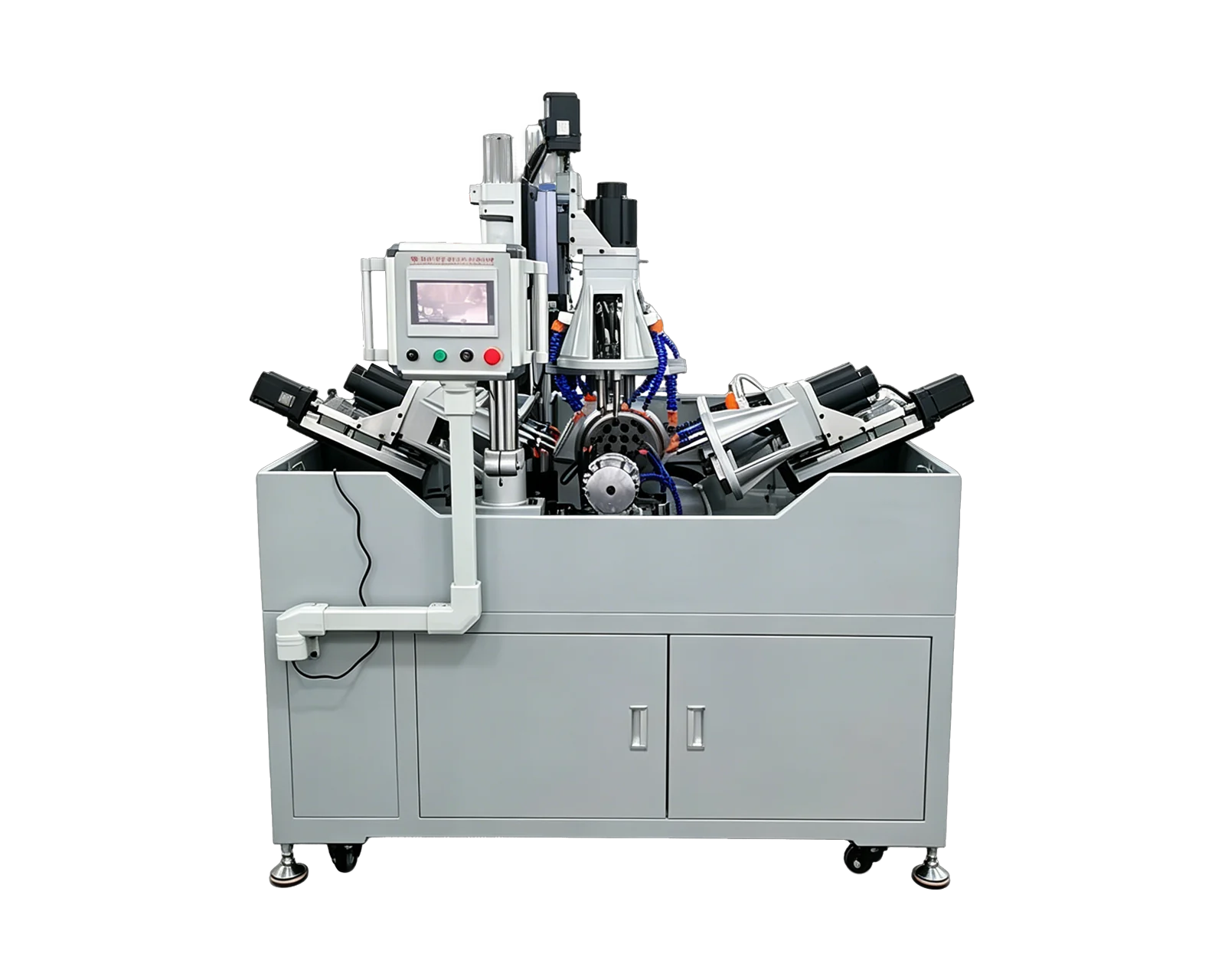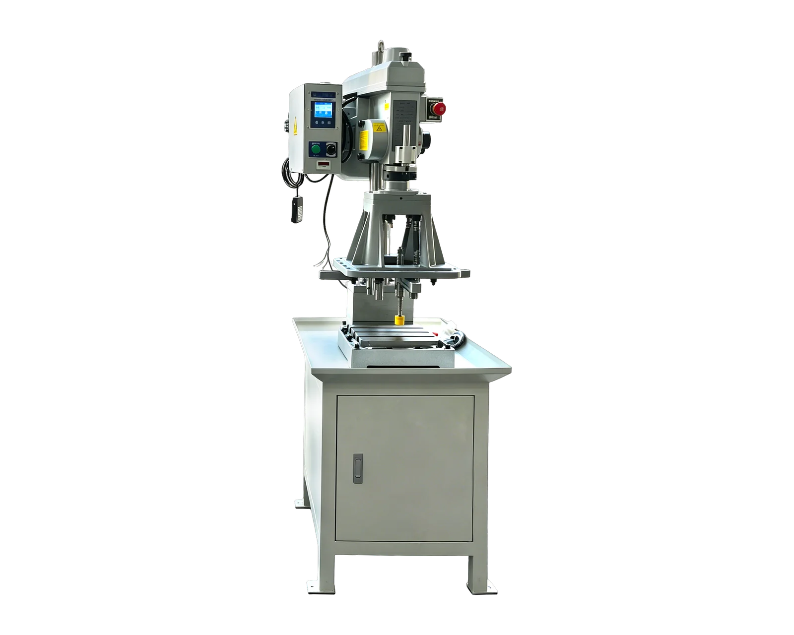
Explore equipment for your inquiry
4508 Gear-Driven Automatic Tapping Machine →Review the published specifications and configuration options against your part drawing before requesting a quote.
Resolve the part name with a section drawing
A quotation that asks for a barrel nut with a cross-hole can leave an important ambiguity. In a cross-dowel design, the transverse bore itself may be threaded. In another component, an additional unthreaded bore may intersect a threaded feature. Number every feature on the drawing and state which operation belongs to it. Do not add a second drilling operation solely because two informal names appear in the inquiry.
Fastenright's cross-dowel product description shows a cylindrical nut with a thread through its sides and an end slot used for orientation during assembly. Its separate twin-hole version illustrates why hole count also needs to be explicit. These product examples clarify terminology; they do not define the dimensions, tolerances or machining method for the part you intend to manufacture.
Connect the thread axis to the body and orientation feature
Show the body axis, the end reference used for hole location and the transverse thread axis. Identify whether the hole is centered along the length or offset according to the drawing. If a slot, flat or mark is intended to indicate the thread direction, specify the required relationship through the design owner. A visually similar slot is not sufficient evidence of that relationship.
Use this original feature map to separate geometry from process assumptions. For a two-hole version, give each hole its own identity and include the specified relationship between them. Avoid relying on a product photograph to infer symmetry, spacing or a common drilling setup.
Establish orientation at the stage where it becomes necessary
A plain cylindrical blank may not yet have a meaningful angular orientation. The process proposal should explain when that changes: an existing slot might locate the blank, or the slot might be produced later relative to the completed bore. Compare the proposed sequence with the drawing instead of assuming that a feeder can identify a direction that has not yet been created.
Also distinguish angular orientation from end-for-end orientation. An offset bore or unequal end features can make reversal important even when the outside diameter is unchanged. Ask for a loading and retention concept that names the observable features it uses. Automatic feeding suitability needs representative parts and an application review; the part's small size alone is not confirmation of a workable feeding system.
Preserve the hole identity between drilling and tapping
State whether drilling and tapping share a location or require a transfer. Describe how the prepared hole is presented to the tapping operation and how mixed part versions are kept identifiable. The tooling review should consider the actual curved entry and exit surfaces, material and required thread extent. It should determine the process details from those inputs rather than copy settings from a generic nut example.
For a genuinely separate intersecting bore, add its machining order and intersection condition to the review. Identify who evaluates any remaining burr and how the finished condition is inspected. Do not assume that passing a tool through the second bore supplies an accepted deburring operation. If a downstream coating or other finish is specified, show the final acceptance stage and responsibility for its effect on the supplied component.
Evaluate geometry and assembly observations separately
A hypothetical trial might produce a thread that passes its agreed inspection while the orientation slot is not related to the bore as the drawing requires. That result calls for a feature-relationship investigation, not an automatic change to tapping settings. Preserve the sample identity and record which requirement passed and which did not. Keep the proposed corrective action tied to the affected operation.
For the equipment inquiry, send the section drawing, all variants, material condition, incoming blank photographs and annual or batch quantities. Include representative samples and the planned inspection methods. Ask BINSING to review the defined drilling and tapping scope, with any slot-making, finishing or assembly observation listed separately. A catalog machine image is a discussion reference and does not establish an approved barrel-nut production process.