
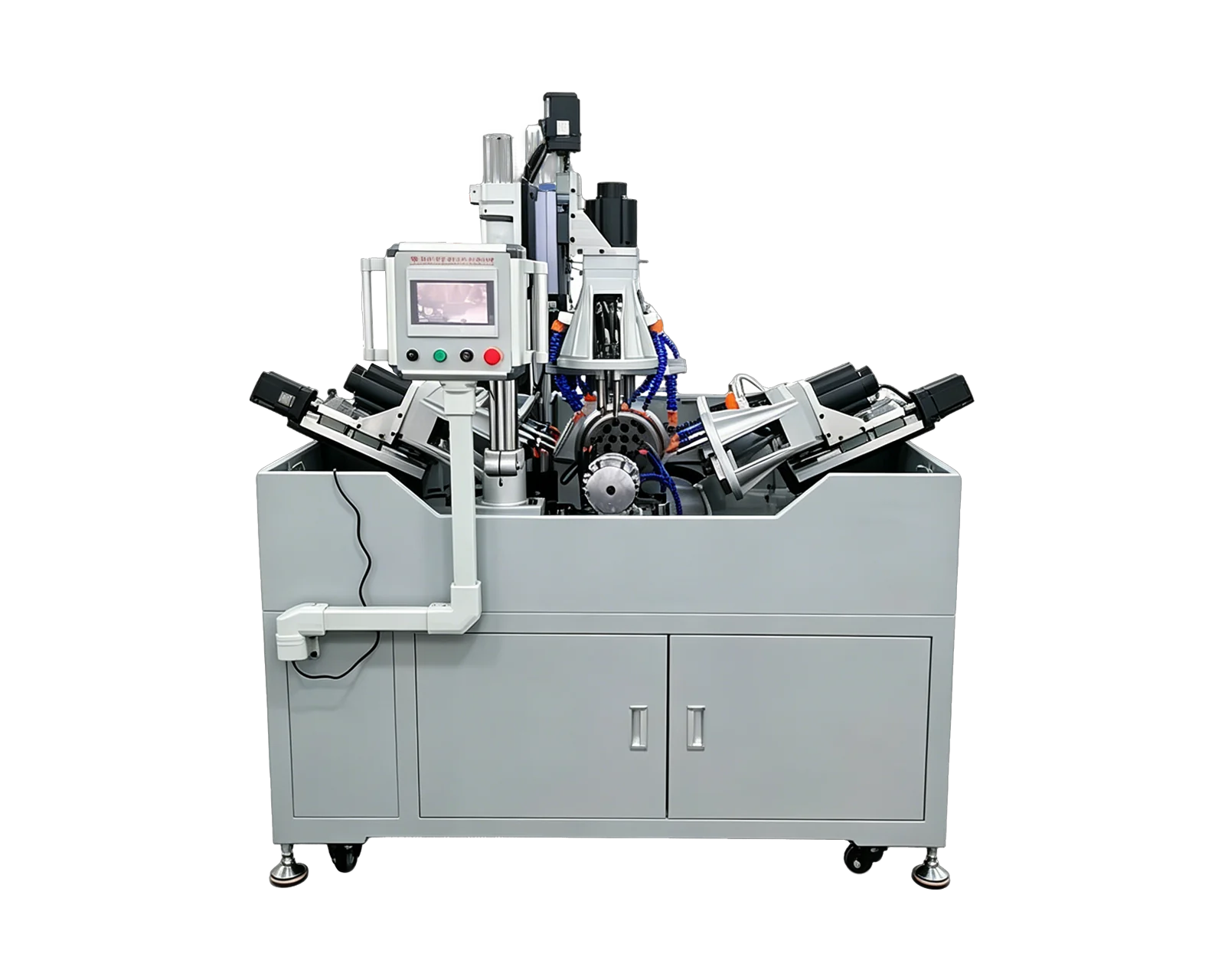
Explore equipment for your inquiry
Dual-Servo Multi-Spindle Drilling & Tapping Machine →Review the published specifications and configuration options against your part drawing before requesting a quote.
Start with the axle relationship on the finished fork
For a caster fork with two cheeks, mark the axle holes, the space between the cheeks and the mounting reference on the finished drawing. Ask the design owner which dimensional and geometric relationships govern acceptance. A hole diameter on the flat blank is only one part of that definition. Keep any wheel, axle or bearing assembly requirements separate from the machining station's component checks.
Rime's sheet-metal guidance explains that holes near a bend can deform during bending and discusses their distance from the deformation area. That principle makes the hole location relative to the bend an early review input. It does not supply a universal distance or prove that an existing caster design needs to change. The material, drawing and actual forming route need their own assessment.
Compare the same finished requirement through two routes
Prepare a route sheet for holes made in the blank and another for holes made in the formed fork. Show any intermediate hole, later finishing or deburring step explicitly. Avoid comparing a completed operation in one proposal with a partly finished feature in the other. The table below is an original inquiry worksheet; it does not rank the routes before a trial.
Keep fixture restraint separate from the finished shape
Document how the proposed fixture locates the formed bracket and where it supports each cheek. Ask whether loading requires the operator to squeeze or spread the fork. If so, the reviewer needs to understand whether that changes the relationship being machined or measured. A photograph of a firmly clamped part cannot establish the geometry it retains after release.
Agree when inspection takes place and which references it uses. For example, the trial record can distinguish incoming free-state shape, located machining condition and released-part results. The responsible engineer should specify the actual measurement method and acceptance limits. This separation helps the team investigate a difference without assuming that either bending or drilling is automatically responsible.
State whether the cheeks are machined together or separately
Show the proposed tool direction for each axle hole. A route that passes through both cheeks and a route that approaches them separately have different access and support questions. Review the intervening space, the entry condition at the second cheek, the tool holder clearance and the planned exit-burr treatment. Do not infer a suitable tool path from an outside photograph alone.
If the part is reoriented, identify how the second setup recovers the drawing references. If both sides are held at once, record what establishes their position. Ask the supplier to describe the sequence before comparing machine counts or advertised cycle times. These questions concern the bracket operation; they do not establish finished caster load capacity, rolling performance or suitability for a particular environment.
Use traceable blanks and formed samples to settle the comparison
In a hypothetical route trial, label one sample group before forming and retain its results after forming. For the second group, record the incoming formed condition before drilling. Use the same finished drawing and agreed inspection approach for both groups. Keep material and forming records attached so that an unexplained difference is not hidden inside a simple pass-or-fail total.
Record handling time, rejected parts, extra setups and any operations still required downstream. A fast hole-making step may leave substantial work elsewhere in the route. Send BINSING the blank and formed drawings, actual samples, quantity and required axle-hole relationship to discuss machining suitability. Request a proposal with a defined incoming stage and final inspection boundary, while forming and caster-product approvals remain with their responsible owners.
