Explore equipment for your inquiry
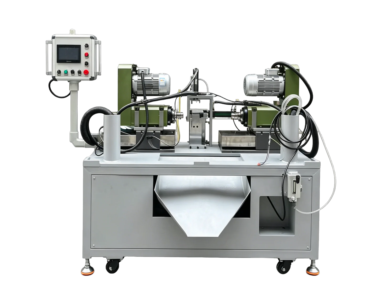
Horizontal Double-Head Drilling Machine →Review the published specifications and configuration options against your part drawing before requesting a quote.
1. Name the part that will be machined
An industrial pull handle can use separate mounting feet, end blocks or another attachment arrangement. Identify the actual component being quoted with its own drawing and part number. State whether it is loaded loose or attached to the handle. A photograph of the full assembly helps explain orientation, but it does not define which faces are accessible during the proposed operation.
Provide material, incoming condition and any existing finish. Mark the requested holes and threads on the component drawing, then identify the mating item for each feature. Keep the handle-to-mount connection separate from the mount-to-panel connection when both appear on the same part. The supplier should be able to see which operations belong to the equipment inquiry without choosing the assembly construction.
2. Describe blind and through features end by end
Do not use a general statement such as drill both ends when the ends have different requirements. Identify entry faces, hole depth and usable thread depth using the drawing's references. State whether a feature passes through, stops within the component or arrives partly complete. This schedule organizes the inquiry; the controlled drawing remains the source of the engineering requirements.
3. Control the pair and interface version together
Explain whether the two mounts are identical, handed or assigned to different ends of the handle. Where several handle lengths share a mounting component, identify what actually stays common and what changes. A matching outside shape does not prove a common internal thread or attachment direction. Supply a simple combination list linking each handle revision to the approved mount part numbers.
If the buyer supplies mating hardware, label its part number and purpose. Hardware intended only to illustrate the assembly should not silently become the inspection method. Agree the feature checks and any separately requested assembly check in advance. For finished appearance surfaces, identify the acceptable condition at handover and show which surfaces will remain visible after assembly. Ask the supplier to review those requirements with the actual supplied finish.
4. Resolve a blind-end change before comparing layouts
Hypothetical purchasing example: two mount versions have the same outside dimensions, but one has a blind threaded feature while the other has a through opening. An inquiry photograph makes them appear interchangeable. The buyer should label the versions and send separate feature definitions before asking whether a shared machine arrangement is suitable. A result from the through-hole version does not establish the required endpoint for the blind version.
A horizontal double-head drilling platform may be a useful discussion starting point when two end features need review. Its catalog name does not confirm tapping scope, suitability for an assembled handle or coverage of every mount version. Ask the supplier to respond to the defined operations and loading condition. Compare any proposed alternatives against the same parts and evidence, including operations that would remain elsewhere.
5. Define component acceptance before a handle assembly trial
Agree the hole and thread checks for each mount and specify how results identify the version and member. If an assembly sample is also requested, state what it is meant to demonstrate and who reviews it. Installation, load and durability requirements belong to the responsible product evaluation; they should not be inferred from a satisfactory thread check or a photograph of a completed assembly.
Email BINSING the mount drawings, end-feature schedule, interface combination list and incoming-stage photographs. Include quantities by version and explain whether paired items must remain together. Request an application review that identifies the proposed machining scope and any missing evidence. This gives purchasing a clear basis for comparing component operations while keeping the complete handle's performance requirements with the team responsible for validating them.