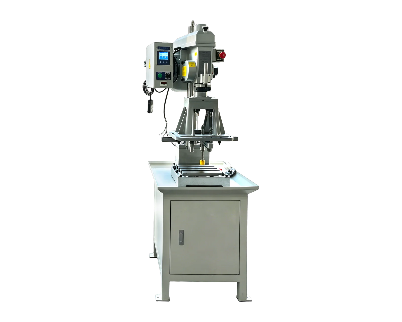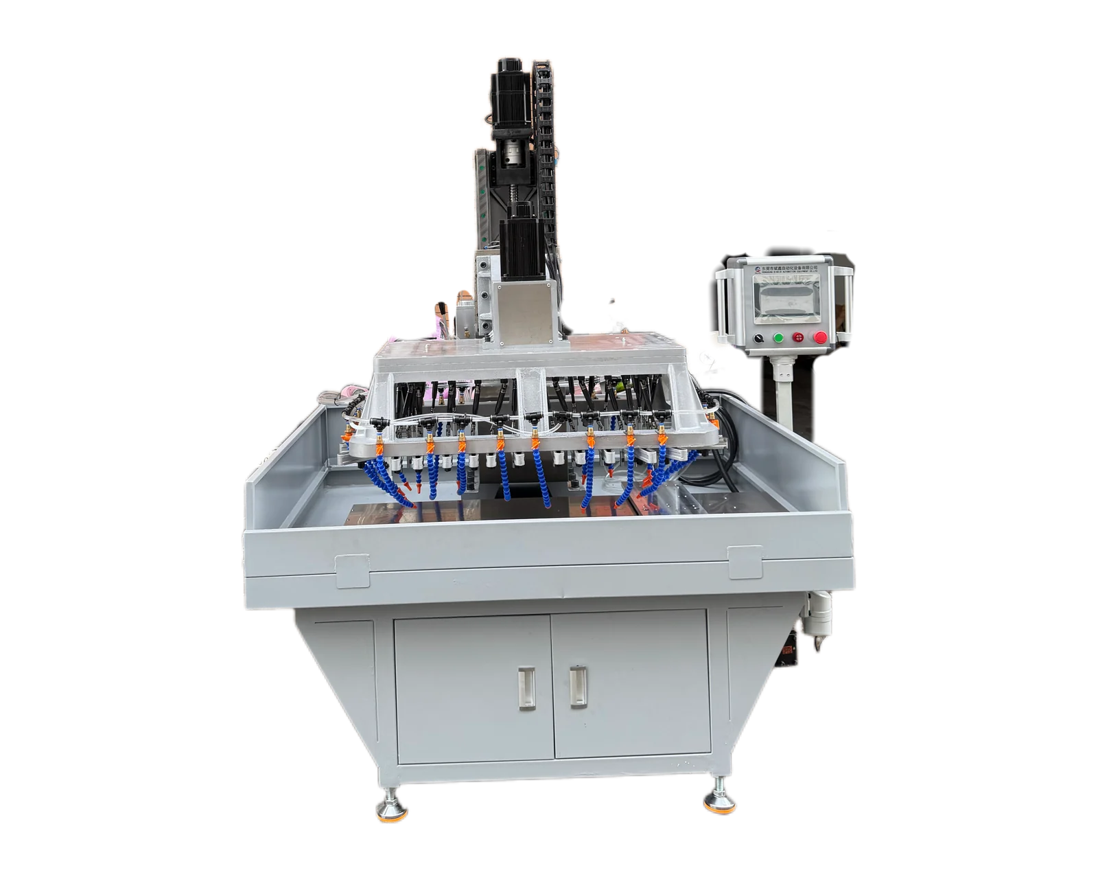
Explore equipment for your inquiry
Servo Traverse Multi-Spindle Drilling & Tapping Machine →Review the published specifications and configuration options against your part drawing before requesting a quote.
1. Identify the body rather than the complete gauge
A gauge assembly may contain a body, replaceable contacts, locating items and measuring elements. Name the component that the machine will receive and supply its released drawing. Include material, revision and the upstream operations already completed. State whether the body is bare or has attached items, and distinguish a photograph of a complete gauge from an image of the actual incoming workpiece.
Mark the fixing holes and threads requested for quotation. Separately identify features that locate measuring elements or establish a measurement reference. Their appearance on the same drawing does not mean they share the same process or acceptance method. If a feature needs a later finishing operation, name the process owner and state what condition the drilling operation must hand over.
2. Allocate each reference and attachment feature
A useful inquiry distinguishes the feature being produced from the function it serves in the finished gauge. Ask the buyer's design or quality team to identify the controlled requirements. Avoid asking the machine supplier to infer a measurement system from an assembly photograph. Use a feature-level register to capture the division of work before comparing equipment proposals.
3. Make the inspection condition part of the handover
State when body features will be checked relative to treatment, finishing and assembly. If a reference face exists before drilling, identify its condition and the buyer's criteria for preserving it. If it will be produced afterward, explain which references are available during the proposed operation. These details help the supplier review the task without treating an unfinished surface as an approved inspection reference.
Provide the measuring-element interface document when it is needed to understand the body drawing, but identify who approved the relationship between the two. A purchased element part number does not replace the body feature definition. Record whether a supplied element is for visual context, a specified fit check or later assembly. Keep its intended use explicit so a successful trial does not acquire an unagreed measurement claim.
4. Keep component results separate from gauge approval
Hypothetical purchasing example: a body contains tapped holes for a cover and a separate seat for a measuring element. The trial request covers the cover threads, while the seat will be finished by another supplier. The buyer should accept or question the thread results against the agreed body requirements. Those results cannot close the separate seat-finishing task or approve the measurement behavior of the assembled gauge.
If the buyer later adds the seat to the equipment inquiry, issue a revised feature list and request a fresh scope review. Identify the required endpoint and evidence rather than describing the addition as another hole. Preserve the earlier trial record under its original scope. This makes it possible to see which component questions have been answered and which still depend on another operation or assembly stage.
5. Request a proposal around the body work actually needed
List body versions by drawing revision and feature differences. Similar outlines may conceal a changed measuring-element location, attachment direction or reference arrangement. Give expected quantities by version and identify which representative bodies are available. Ask the supplier to explain the covered operations, proposed changeover items and unresolved sample needs. Keep any final gauge verification outside the component acceptance record unless it has been explicitly defined and assigned.
Email BINSING the body drawings, incoming-stage images and feature responsibility register. Include the relevant interface documents with their revisions and identify the buyer's review contact for reference questions. A focused drilling and tapping discussion can then establish what the proposed equipment must produce and what evidence is required at handover. Final measurement accuracy and calibration need their own agreed requirements and responsible verification process.