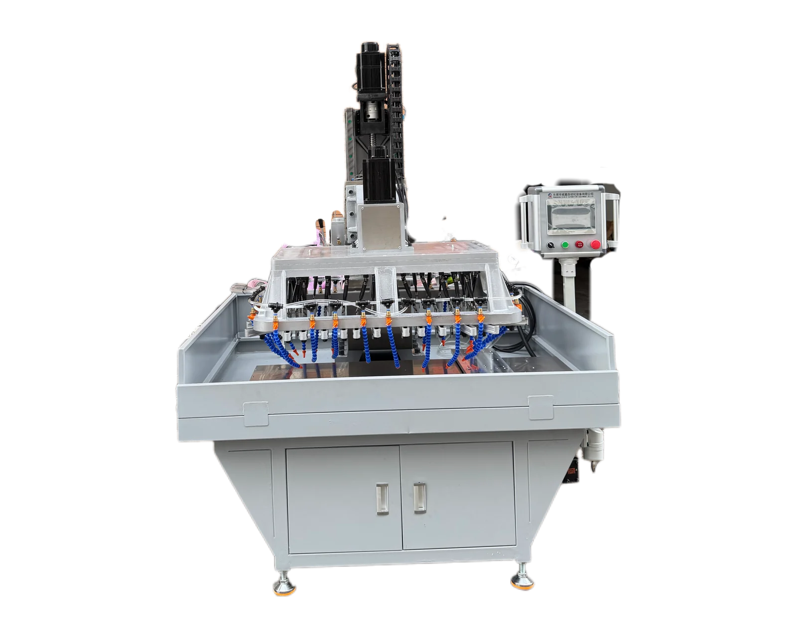
Explore equipment for your inquiry
Automatic Drilling & Tapping Machines →Compare standard platforms and custom layouts, then prepare the part and production requirements for your quote.
Identify the stroke and units before calculating
Start with the actual motion to be timed. A drawing's hole depth, full-diameter depth and required full thread depth are not automatically the same as tool travel. Identify where feed starts, where it ends and which return movement is included. Use positive travel distances and speed magnitudes in these estimates.
Obtain suitable speeds and feeds for the material, tool, hole and machine from the responsible tooling or process specialist. The numbers below are hypothetical arithmetic examples, not recommended cutting conditions or BINSING performance claims.
Drilling time: divide feed travel by feed speed
Use v = n × f, then t = 60 × L / (n × f). The factor 60 converts minutes to seconds. KEYENCE's drilling formulas relate spindle feed, revolutions and feed per revolution in this way. Keep all lengths in mm for this version; do not combine inch travel with metric feed.
In a hypothetical single uninterrupted feed stroke, L = 24 mm, n = 1200 rpm and f = 0.12 mm/rev. The axial feed speed is 1200 × 0.12 = 144 mm/min, so t = 60 × 24 / 144 = 10 seconds. This is the feed-stroke estimate only; rapid approach, withdrawal and any pause are outside it.
The 24 mm is an assumed total feed stroke, not a specified plate thickness. When planning a through hole, determine the travel needed for the required diameter to break through, using the actual point geometry and clearances. If the programmed endpoint already includes that distance, do not add it again. For a blind hole, check the permitted bottom geometry before extending travel.
Tapping time: include both forward and reverse travel
For a single-start thread, axial advance per revolution equals pitch p. At a constant spindle speed, v = n × p. Estimate the two directions as t_in = 60 × L_in / (n_in × p) and t_out = 60 × L_out / (n_out × p). Their sum is the constant-speed forward-and-return travel estimate, before extra reversal and acceleration time.
For a hypothetical M8 × 1.25 operation, assume an 18 mm forward stroke and an 18 mm return, both at 600 rpm. The feed speed is 600 × 1.25 = 750 mm/min. Forward travel takes 60 × 18 / 750 = 1.44 seconds; return travel also takes 1.44 seconds, giving 2.88 seconds in total. This does not establish an 18 mm full thread depth: tap lead, approach position and bottom or exit clearance must be defined separately.
Use the actual approved return speed rather than assuming it matches the cutting speed. Haas documents a retract-speed setting for its rigid-tapping controls, illustrating why the return assumption matters; it is not a setting instruction for BINSING equipment. For multi-start threads use lead rather than pitch. Confirm the machine's feed mode and synchronization requirements instead of copying these planning formulas into a controller program.
Convert motion estimates into a complete cycle
For a fully serial route, add the durations of the consecutive activities. Where activities overlap, place them on a timeline and count elapsed time only once. Replace ideal motion estimates with observed or validated machine motion times when available; do not add an entire measured motion interval on top of the estimate for that same interval.
For short strokes, acceleration, deceleration and reversal can make constant-rpm arithmetic differ substantially from elapsed time. Additional time is the amount not already represented by the motion model. There is no universal percentage allowance that can establish a complete machine cycle.
Count sequences and overlapping groups, not just holes
For identical holes machined one after another, multiply the per-hole motion estimate by the number of holes, then include travel between positions and other omitted activities. Different hole depths or cutting conditions need separate calculations.
If two independent operations start together and last 10 and 14 seconds, their overlapping phase lasts 14 seconds, not 24. This hypothetical timing example assumes both can actually run concurrently. It does not establish that two tools sharing a feed can use independent speeds or strokes, or that the whole machine cycle lasts 14 seconds. Add transfers and any work that cannot overlap; refer to the simultaneous-versus-sequential guide for grouping feasibility.
Check the estimate against the intended production route
Keep a simple worksheet with the hole reference, stroke, units, speed, feed or pitch, estimated time and excluded activities. Label every input as assumed, supplier-confirmed or measured. An unknown allowance remains unresolved rather than becoming zero.
During an application trial, compare the planned and observed intervals using the same start and finish events. Record multiple cycles and whether the completed parts pass the agreed checks. Use the separate cycle-time comparison guide to align supplier quotations, and the output-requirements guide to assess demand. Neither accepted hourly output nor investment payback follows from a feed-time calculation alone.