Explore equipment for your inquiry
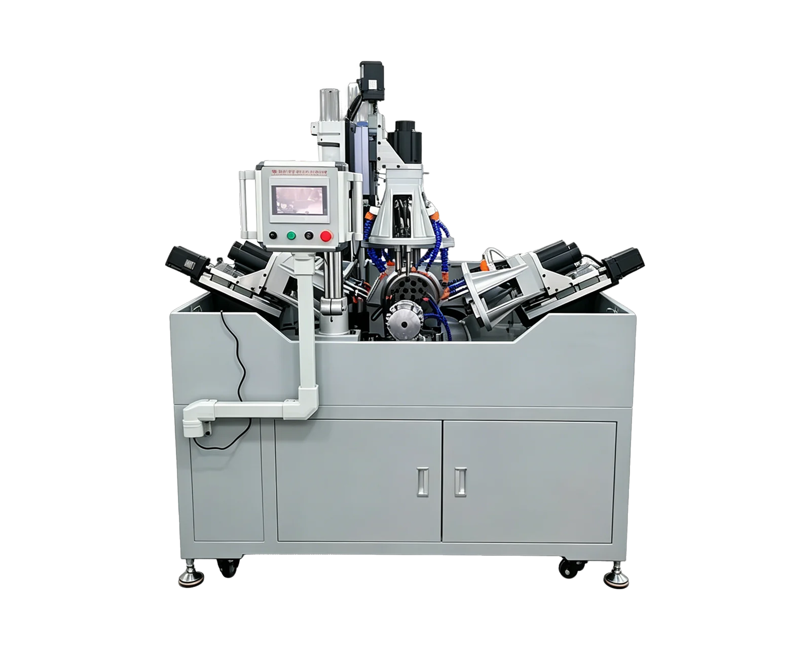
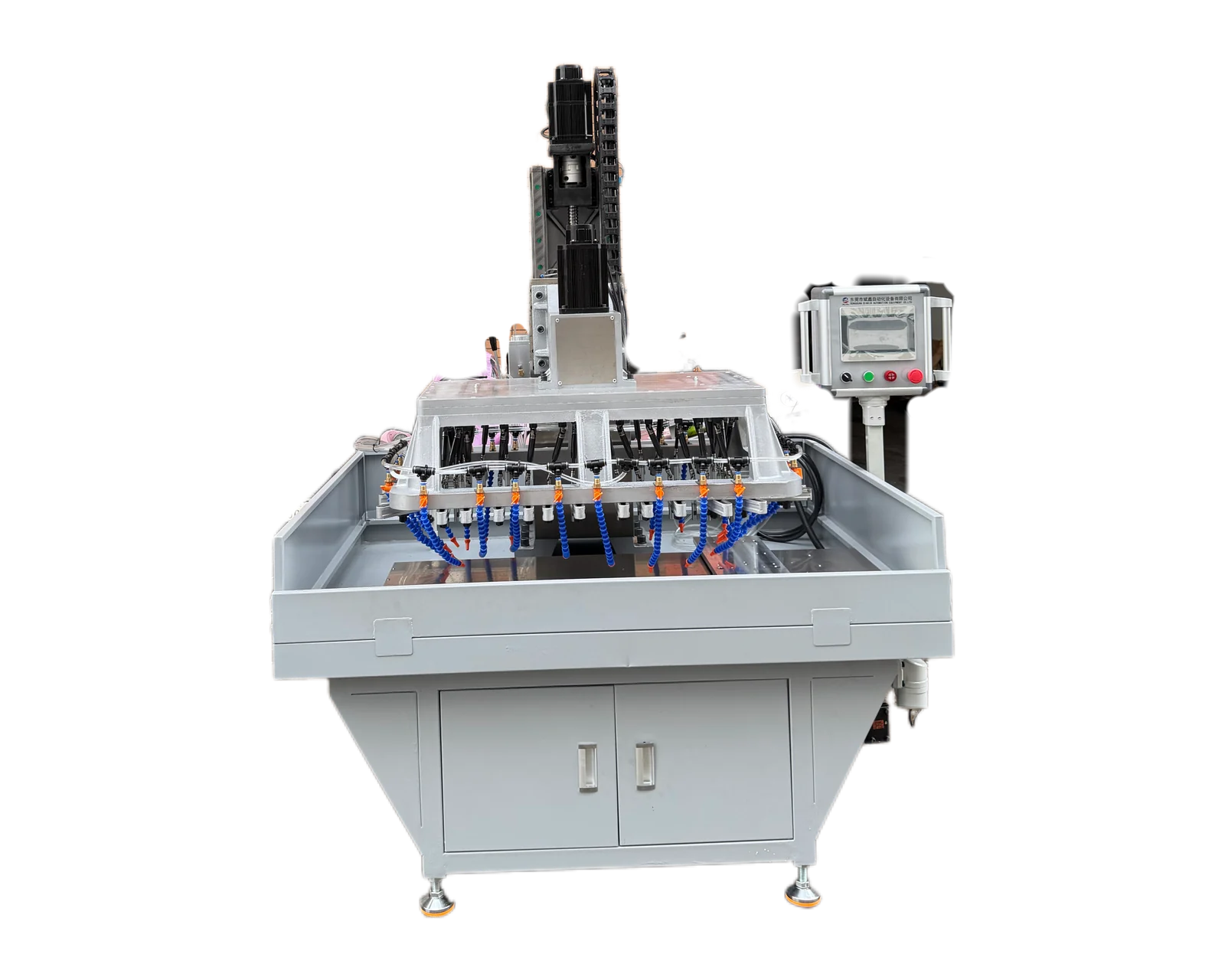
Dual-Servo Multi-Spindle Drilling & Tapping Machine →Review the published specifications and configuration options against your part drawing before requesting a quote.
1. Use a part reference to define direction
Terms such as sensor side and machine side can become ambiguous when a bracket is turned over or used in another installation. Supply the controlled component drawing with face identifiers and the approved relationship between mounting holes and sensor-interface features. Add photographs that show the incoming part in the same orientation as the drawing.
If the bracket is supplied after forming, welding or other machining, describe that incoming stage and identify the existing features. Do not use an assembly illustration to imply that the supplier must create every visible opening. Highlight the specific drilling and tapping tasks.
2. Distinguish mounting holes from adjustment features
A sensor mount may combine fixing threads, clearance holes and features intended for mechanical adjustment. List their functions separately, using the drawing as the authority. In particular, an adjustment slot should not silently become part of a drilling and tapping package. State whether it arrives complete, is made by another process or needs a separately reviewed operation in the proposed equipment.
3. Show which reference surfaces are already complete
Mark any faces or features completed before the proposed drilling and tapping operation. Explain their drawing-defined role and give the incoming condition required by the process owner. Ask the supplier to identify the references assumed in the equipment concept. A visually convenient edge should not substitute for a specified reference merely because it is easy to point out in a photograph.
State restrictions on contact with finished or appearance-sensitive areas and identify how their condition will be assessed at handover. Where a slot is finished elsewhere, explain whether it exists before or after the quoted operation. This sequence can change what information is available for the workholding review. It also establishes who must resolve a disagreement if an incoming feature does not match the released requirements.
4. Keep interface revisions attached to the bracket version
Hypothetical purchasing example: a buyer uses the same bracket outline for two sensor interfaces. One version changes the fixing-thread arrangement while retaining the base mounting holes and adjustment slot. The buyer sends a sample of the older version with the newer drawing. Without explicit identification, a trial could demonstrate the wrong thread arrangement while appearing to cover the common bracket shape.
Prepare a short version table linking bracket part number, drawing revision, interface designation and sample identity. Ask which versions are included in the quotation and which remain provisional. The supplier should review the mechanical machining requirement supplied by the buyer. Selection of the sensor, its detection behavior and the suitability of its installed position belong to the responsible product or system team, not to an assumed outcome of bracket machining.
5. Define a component-level trial and quotation
Request evidence for the specified hole positions, thread requirements and preservation of existing references. If a mating-item demonstration is desired, identify the exact item and the limited purpose of that check. Keep separate any adjustment, calibration or system validation performed after installation. A bracket that meets its agreed component checks has not thereby demonstrated every function of the equipment that later uses the sensor.
Email BINSING the mount drawing, incoming-stage views, feature responsibility register and version list. Include production quantities for each bracket version and identify the sample available for review. Ask whether a standard drilling and tapping platform should be assessed for the defined task and what additional work remains outside it. A useful response names the included operations and dependencies instead of relying on the broad phrase sensor bracket machine.