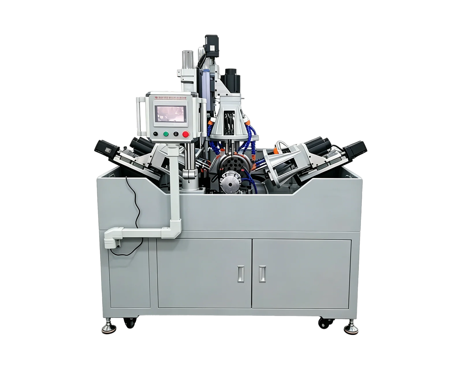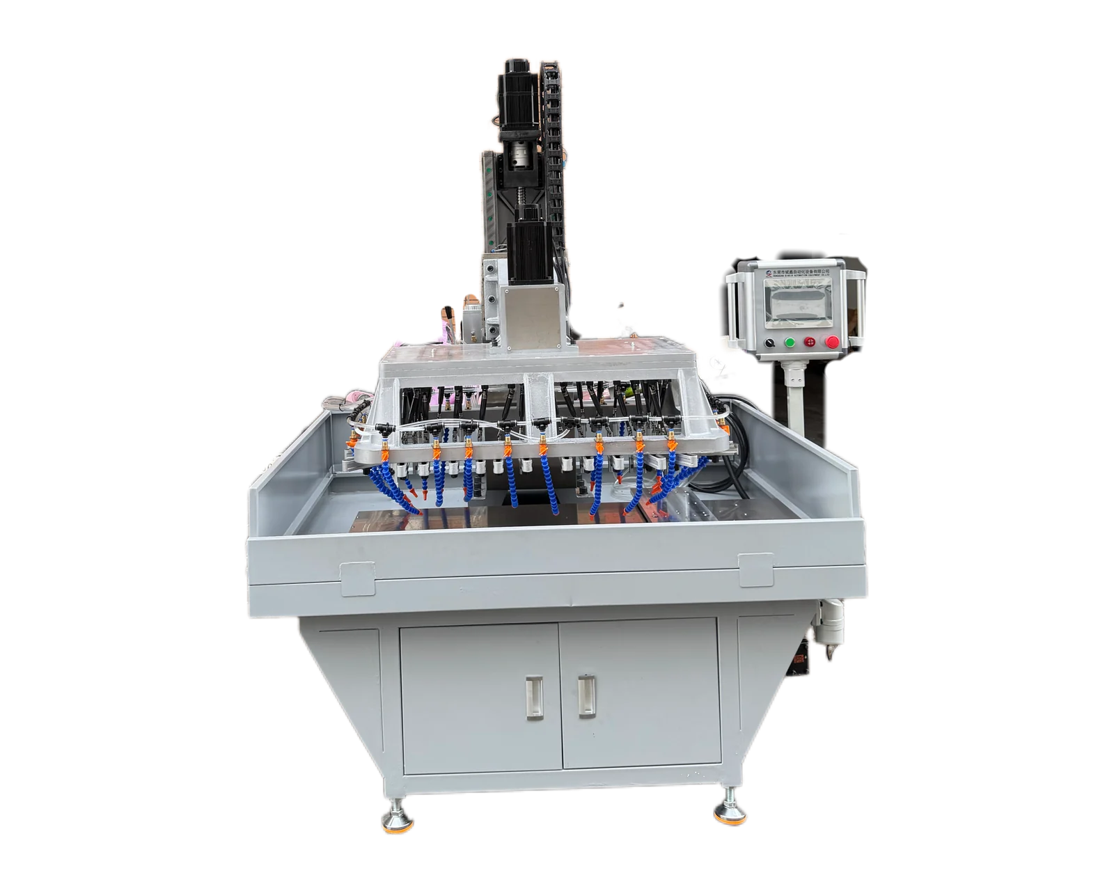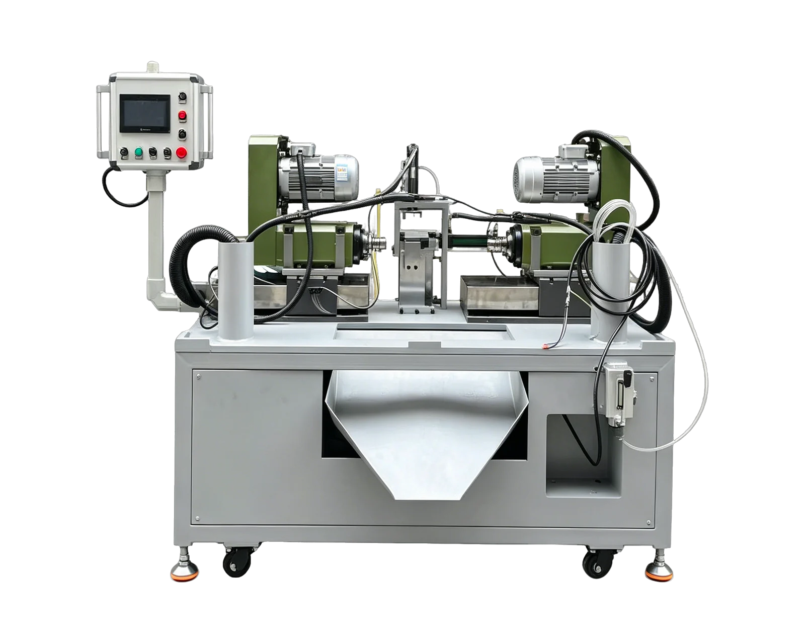
Explore equipment for your inquiry
Horizontal Double-Head Drilling Machine →Review the published specifications and configuration options against your part drawing before requesting a quote.
Mark the hole axes before choosing a machine
Place the drawing beside a photograph showing the incoming part in a stable, supported position. Mark each hole axis, the face it enters and whether the hole is blind or through. Then sketch the same part in the proposed fixture. A hole shown vertically on a drawing does not require a vertical machine: drawing orientation and the installed orientation are separate decisions.
For a long component needing work at both ends, a horizontal arrangement is one layout to investigate. For holes entering a readily accessible upper face, a vertical arrangement may be a useful starting point. These examples identify alternatives for review; neither proves that a particular machine fits. Tool reach, part support, clamping and the finished-hole requirements remain part of the assessment.
Compare access at every stage, not only during cutting
Ask each proposal to show the incoming part, the clamped position and the finished part leaving the station. Use the same drawing revision and operation boundary. The worksheet below helps expose a layout that makes machining look simple while transferring difficult handling or cleaning tasks to the operator. Enter dimensions or observed actions rather than a general 'suitable' response.
Treat chip removal as a process requirement
Sandvik Coromant's official film on chip formation in indexable drilling identifies poor chip evacuation as a cause of surface problems, tool breakage and component damage. Its CoroDrill DE10 product information also describes flute geometry and coolant passages as features associated with chip evacuation. These sources support checking the cutting tool and coolant arrangement; they do not establish that changing machine orientation alone solves a chip problem.
During the proposed trial, observe where chips remain after machining, after unclamping and before the next part is seated. Include blind features and fixture pockets in the inspection. Record any cleaning activity and who performs it. Ask the supplier to confirm the actual coolant and chip-handling scope rather than assuming a photograph includes a particular filtration or extraction system. External tool-maker information is background, not a specification for a BINSING machine.
A useful comparison can end with an unresolved layout item
Hypothetical orientation comparison: a bracket has a hole entering one face and a protected surface used for assembly. Sketch the same bracket in two supported positions, presenting the hole to a vertical approach in one and a horizontal approach in the other. Mark the locator contacts, clamp access, holder envelope and through-hole exit in each sketch. Turning the part changes those relationships even though the drawing requirement stays the same.
Keep the incoming condition and finished operation identical in both proposals. Record how the part is placed and removed, whether chips collect on the next locating surface and which cleaning actions occur before the next part. Leave missing clearance or handling dimensions open until the layout is revised. The orientation choice remains separate from the number of heads: after choosing candidate approaches, assess whether a single approach, opposing heads or a multi-side arrangement fits the complete feature list.