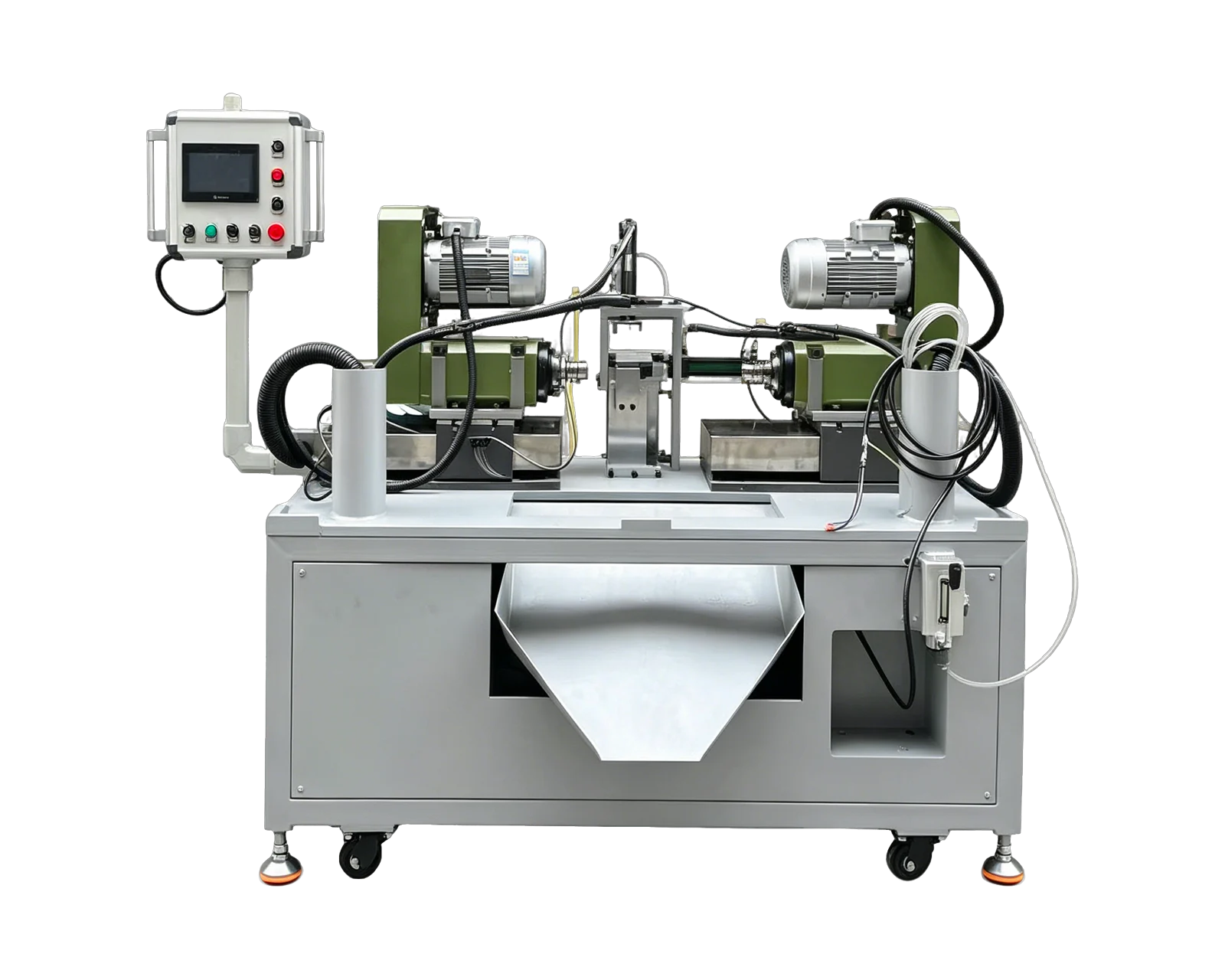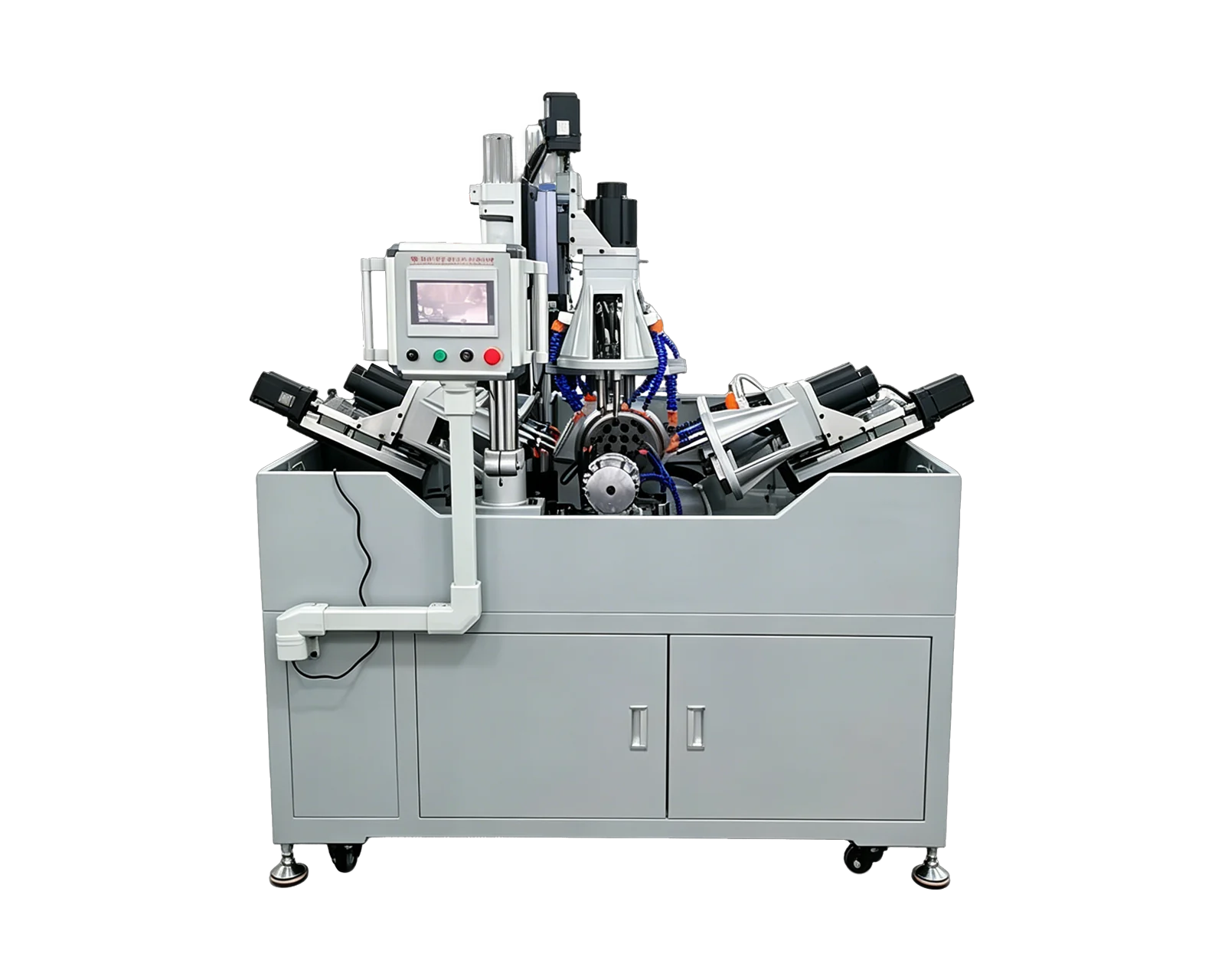
Explore equipment for your inquiry
Multi-Side Drilling & Tapping →Review the layout options and required part information to define the scope of a custom equipment inquiry.
Map every feature to a machining face
Annotate the drawing so each hole, thread and chamfer belongs to a clearly identified face. Include depth, direction and the relationship to the part datums. A perspective image helps explain the shape, but it should accompany dimensioned views when positions and feature relationships matter.
Separate existing features from those the new machine must create. Also show where the workpiece enters the process with excess material, burrs or a partly finished surface. The supplier needs to evaluate the incoming part as well as the desired finished result; otherwise, a convenient-looking locating surface may not actually be available when the part is loaded.
Treat clamping space as part of the layout
Mark which surfaces may touch locators or clamps and which must remain protected. Explain any thin walls, cosmetic surfaces or features that cannot accept clamping contact. Ask for the proposed support and clamp positions to be shown alongside the machining heads, not on a separate drawing that hides possible conflicts.
Review clearance for the complete tool and holder arrangement, including approach and withdrawal. A hole being visible from one side is not enough to establish that the proposed tooling can reach it in the clamped condition. Ask what changes if a longer tool, a different holder or another part variant is needed.
For a hypothetical bracket with top-face holes and side-face threads, mark a proposed top clamp against the side holder envelope. If that clamp must move, ask the layout to show the new clamp state and the references retained at that moment. The review should establish a workable state for each operation, rather than relying on one drawing that shows all clamps closed.
Ask how the operations are coordinated
A machine with heads in several directions does not automatically machine every feature simultaneously. Request a sequence that shows which operations are performed together, which are separated, and what condition must be met before the next step begins. Include any required movement or repositioning of the workpiece.
Where holes meet or operations depend on earlier features, call those relationships out for review. State the finished-part requirement and ask the supplier to explain the planned order and verification. Do not use the number of heads as a substitute for reviewing how the actual part will be processed.
Compare a fixed layout with other arrangements
A vertical-and-horizontal layout is a candidate when the required faces are accessible around a suitable fixture. An indexed arrangement is another direction to review when the part must move through several positions. For parts requiring only drilling at two opposite ends, start by comparing the horizontal double-head platform with the broader custom proposal.
Ask which features can be completed in the proposed setup and which remain outside the machine's scope. Be explicit about any manual repositioning. A single-loading objective is useful to discuss, but it should become an agreed requirement only after the drawing and fixture concept have been reviewed.
Define the finished-part checks before ordering
List the characteristics that matter to assembly, including the relationship between features on different faces. Agree how they will be measured and which inspection equipment or gauges will be used. A machining video can explain access and sequence; it cannot establish dimensional acceptance by appearance alone.
For a family of components, identify the representative variants needed for inspection and changeover demonstration. Ask the supplier to document the included tooling and fixture arrangement, then compare that scope with your full operation list. The goal is a machine proposal with clear coverage and limits, rather than a general promise to machine multiple sides.