The short answer
Use a multi-spindle drilling video to record what is actually visible, label what remains unverified and request evidence for the purchasing decision. A tooling row can illustrate the arrangement, but it does not establish exact spindle spacing, simultaneous cutting, finished-part output or dimensional acceptance. Connect the reference to your drawing, an explained operation sequence and identified inspection results before treating it as application evidence.
Explore equipment for your inquiry
Multi-Spindle Drilling Machines →Compare simultaneous drilling, traverse layouts and custom configurations against your complete hole pattern.
What the published reference establishes
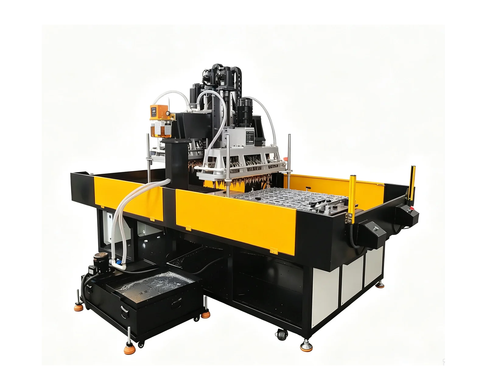
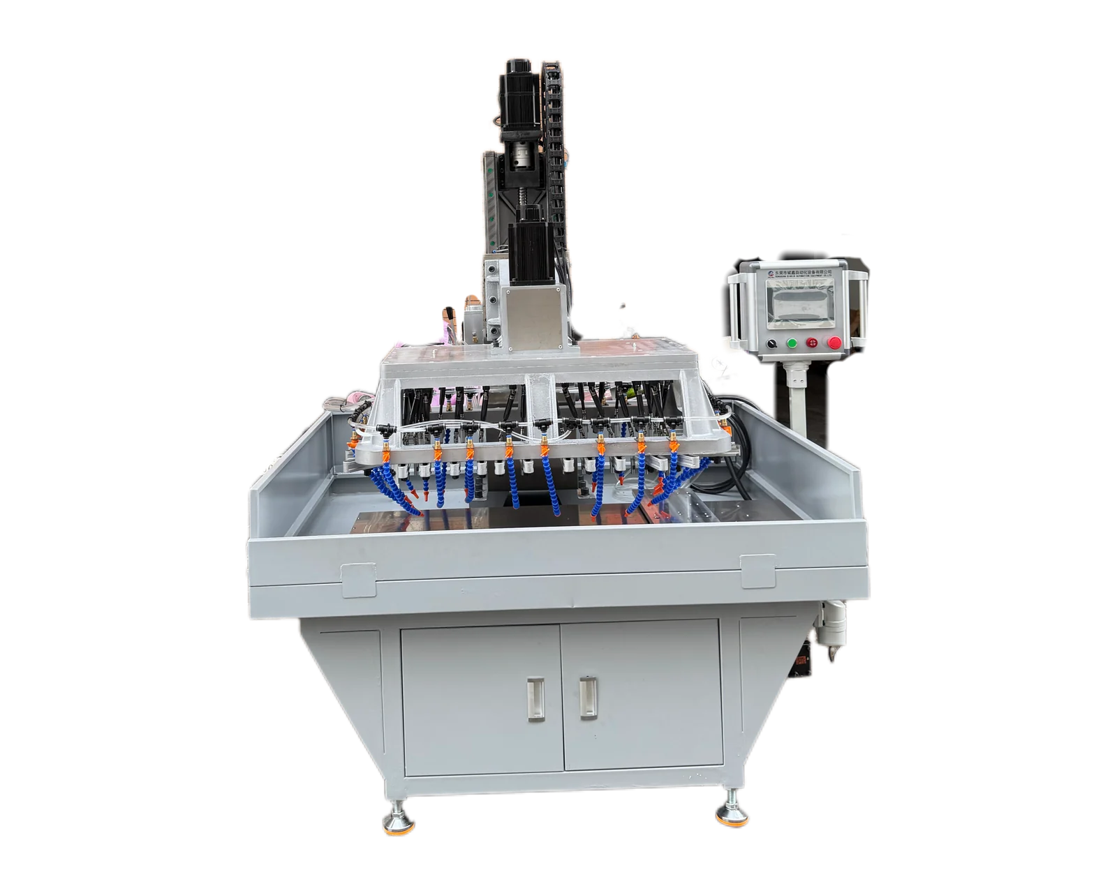
The linked BINSING gantry reference has a wide worktable, a supporting structure above it and a row of tooling positions visible in the reviewed source frame. It is a useful visual starting point for discussing a distributed hole pattern. The source does not supply a controlled part drawing or identify the dimensional relationship between every tool and finished feature.
Use the reference to explain the arrangement you want evaluated. Attach your own annotated drawing rather than estimating tool spacing from the camera view. Perspective, hidden features and workholding can make visually similar patterns quite different engineering problems. The useful purchasing question is how a proposed tooling arrangement would address your identified features and what evidence would demonstrate that relationship.
Build the feature register before counting tools
List each required hole or thread and the operations that create it. Identify the relevant size, depth, thread requirement and position reference in the drawing package. A visible tool count is not a complete operation count: the equipment proposal must explain which operations are combined, which are sequential and whether any features remain outside its scope.
For example, a hypothetical component might have several repeated mounting holes and a separate threaded feature. Keep the threaded feature in its own row even if it appears close to the repeated pattern. This prevents a quotation for one repeated operation from being mistaken for a quotation for the finished component. Identify any preceding or subsequent process and the condition in which the part enters the proposed machine.
Separate visible evidence from the claim you need verified
Use this original review worksheet beside the reference. The visible-evidence column is limited to what the frame or supplied sequence actually shows. Leave an item unverified when the camera view is incomplete; a plausible interpretation is not a measured result. Add the actual timestamp or frame reference for each observation when you review a specific clip.
Video review worksheet: observations, limits and next evidence| Visible evidence or reference | What remains unverified | Evidence to request |
|---|
| Row of tooling positions in the reference frame | Exact centers, usable positions and compatibility with your part | Dimensioned proposed layout tied to drawing features |
|---|
| Worktable and support structure | Access with your part, clamps and tools installed | Application layout and fixture review |
|---|
| A cutting movement, if visible in the supplied sequence | Whether all assigned tools cut simultaneously or hidden stages follow | Annotated operation sequence and an unobstructed demonstration |
|---|
| A finished part shown on camera | Hole size, position, depth or thread acceptance | Identified sample and feature-level inspection report |
|---|
| An apparent cycle or edited highlights | Complete loading, processing, unloading and interruption coverage | Continuous agreed-cycle recording with start and end definitions |
|---|
Turn an obscured feature into an evidence request
Start the discussion with features that differ from the repeated pattern. A recess, raised wall, unequal depth or nearby clamp can affect the proposed approach even when the nominal hole positions appear regular. Supply views that show these details and request an access review. Do not simplify a three-dimensional component to a set of hole centers when the surrounding geometry matters.
For each unclear feature, record the question, the missing view or document, and the person responsible for supplying it. An overhead view may clarify a visible arrangement; it still does not replace a dimensioned layout. Use the linked hole-pattern and fixed-versus-adjustable guides for detailed selection criteria so this review stays focused on evidence gaps.
Make the trial report follow the same numbering
Carry the feature identifiers into the sample inspection record. A single statement that the sample is acceptable is less useful for resolving an unclear feature assignment than results connected to the drawing. Have the quality owner define the measurement requirements and sample coverage. Keep process observations, inspection findings and unresolved features visible as separate entries.
If several parts or positions are involved, label them so that results can be traced back to the proposed fixture and tooling arrangement. Request a demonstration view that explains those labels, supported by a sequence description where the view is obstructed. The reference video remains an illustration of a machine family; the application review is the evidence for the proposed scope on your own component.
Prepare your part information
- Reference clip or frame identified
- Observations separated from assumptions
- Hidden stages and edited sections marked unverified
- Each open claim has a requested view or document
- Inspection results linked to identified samples
Discuss my multi-spindle application →Common questions
Does a similar tool row mean the head will fit my part?
No. The actual spacing, access, operation and fixture relationship need a drawing-based review. Use the video as an arrangement reference and request a proposed layout for your component.
Can I assume all visible tools operate at the same time?
Do not infer the operation sequence from a still view or tool count. Ask the supplier to identify simultaneous and sequential steps in the proposed process and connect them to your feature map.
Sources and further reading
Related equipment and project information
Turn your video reference into a drawing-based inquiry
Send the reference clip, your marked drawing and the claims you need verified. Include material, incoming condition and quantity so the proposed evidence and equipment scope can be reviewed.
Discuss my multi-spindle application ↗