Explore equipment for your inquiry
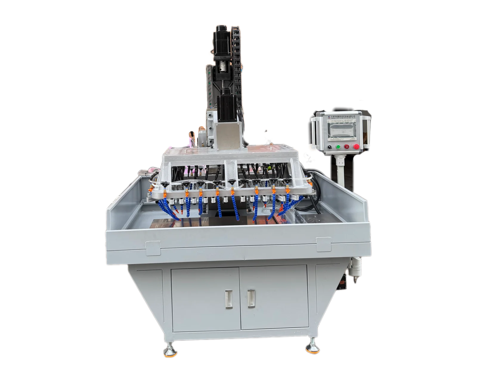
Multi-Spindle Drilling Machines →Compare simultaneous drilling, traverse layouts and custom configurations against your complete hole pattern.
First identify where the power is measured
A quotation may mention electrical supply capacity, motor shaft output or power available at the spindle. Label those separately. Electrical input includes losses before useful mechanical output is produced; a transmission introduces further losses between motor and spindle. Do not insert an electrical-input figure into a spindle-torque calculation and describe the result as available cutting torque.
Create a simple chain for the proposed machine: electrical supply, drive and motor, transmission, then tool spindle. Put each quoted number beside its actual location. If a nameplate value is unclear, request the manufacturer's definition. This prevents two offers with identical-looking kW values from being compared at different measurement boundaries. Accessories and other motors also need to be distinguished from the drive that rotates the cutting tool.
Calculate one mechanical operating point
Sandvik Coromant's drilling formula sheet relates torque to net mechanical power and rotational speed. In SI units, P = T × 2πn / 60,000, where P is kW, T is N·m and n is rpm. Rearranging gives T ≈ 9,550 × P / n. Apply the quantities at the same shaft and operating condition; the rounded constant is a unit conversion, not a machine efficiency factor.
The following original arithmetic example assumes 2.00 kW is actually available mechanically at the spindle at each listed speed. It deliberately compares operating points and does not assert that any motor supplies constant power throughout this range. No material, tool or cutting condition is specified, so the numbers cannot select a machine for a particular hole.
Lower speed does not automatically make more torque available
The table's larger low-speed torque follows from holding power constant mathematically. An actual drive may reach a torque, current or thermal limit instead. If an invented spindle is limited to 20 N·m at 500 rpm, its mechanical output at that point is approximately 20 × 500 / 9,550 = 1.047 kW. Calling its motor 2 kW does not change that limit or establish 38.20 N·m at the tool.
Kollmorgen's motor-data definitions distinguish rated torque at rated speed under continuous operation from standstill and peak-current quantities. Its EKM catalog explains separate continuous and intermittent zones for a motor-and-controller combination, with thermal, current and voltage boundaries. Read the actual proposed system's documentation. A short-duration peak must not become the continuous cutting allowance in a comparison. Request the applicable duration, recovery conditions and repeated-cycle limits from the supplier.
Carry speed and losses through the transmission together
For a second invented example, assume 2.00 kW of motor mechanical output at 1,500 rpm, a 3:1 speed reduction and 90% transmission efficiency at that point. The spindle speed is 500 rpm and spindle power is 1.80 kW. Using the rounded conversion, motor torque is 12.733 N·m and spindle torque is 34.38 N·m. The reduction increases torque while reducing speed; efficiency keeps the output power below the input power.
These assumptions are illustrative, not default gearbox values. If the quotation already specifies available spindle output after transmission, do not subtract transmission losses a second time. For a head driving several tools, also identify each output speed and branch rating. A total drive rating is not a promise that every output can deliver the full total simultaneously. Ask the supplier to map the proposed simultaneous load to the actual drive arrangement.
For a multi-spindle head, compare both the combined demand and each output's limits. The hypothetical worksheet below assumes four estimated mechanical cutting-power demands at the tool outputs during the same interval. The two groups total the same power, but group B concentrates more demand at output S1. Neither group is approved by this arithmetic: output speed, torque rating, transmission limits, duty and losses still need review. These are invented loads, not BINSING ratings or cutting recommendations.
Request the curves that answer your operating question
Give the supplier the proposed operation and required speed range, then request the matching drive evidence. The worksheet below separates unanswered rating questions from cutting-load estimates. A torque curve can describe available drive output, but it does not establish fixture rigidity, axial-feed capacity, tool suitability or finished-hole quality. Those remain part of the application assessment.