Explore equipment for your inquiry
Multi-Side Drilling & Tapping →Review the layout options and required part information to define the scope of a custom equipment inquiry.
1. Identify every wall covered by the drawing
Give each feature an identifier and show it in a section view. State whether it stops at the near wall, continues through the opposite wall or forms part of a separate feature on another face. Include the drawing references that control size, position and the relationship between opposite openings. If the drawing is ambiguous, resolve that ambiguity with the product owner before asking equipment suppliers to price different interpretations.
Distinguish two openings that merely share a projected position from a requirement that controls their common alignment. Also identify threads, counterbores or other finished details separately from the drilling operation. The quotation should name the completed features rather than use a broad description such as drilling through tube.
For square and rectangular sections, label the faces in a consistent end view and retain those labels on every feature map. Other hollow sections need their own geometry and orientation review; a rectangular-section illustration does not establish coverage for round, open or asymmetric profiles.
2. Describe the incoming hollow section
Send the profile drawing together with the incoming part specification. Include the material designation, section dimensions, wall requirements, cut length and any seam or other orientation feature relevant to the drawing. State which values are controlled by the incoming specification and which are observations from samples. A supplier needs to understand the accepted range, rather than design around one unusually regular demonstration piece.
3. Review support and access together
Request a concept showing the full profile, machining directions and proposed locating surfaces. Ask how the concept accounts for the specified incoming section and which surfaces may contact the workholding. Where an internal support is proposed, identify access through the ends, restrictions elsewhere in the component and who supplies the support assembly. Leave the detailed engineering solution to the reviewed proposal instead of prescribing it from an external photograph.
For a part family, compare changes in section size, length and end condition. A closed end or attached fitting may change the available internal access even when the external hole pattern is unchanged. List those variants explicitly. Any shared-fixture proposal should explain the configuration items required for each variant and the features included, so purchasing does not mistake a similar outside shape for confirmed common tooling coverage.
4. Specify what must be checked inside
Define the finished internal condition in the purchasing package. If the product drawing or approved quality plan includes requirements for internal edges, retained chips or interior surfaces, reference those requirements directly. Ask which checks can be demonstrated and what access or sample preparation is required. Separate inspection from any additional finishing or cleaning work; an offer to inspect an interior feature does not include every operation needed to produce it.
Hypothetical purchasing example: two buyers request the same visible hole pattern in a rectangular section. One needs holes in the upper wall only; the other needs related openings across upper and lower walls and documented internal inspection. Their equipment scope is different despite similar outside views. A section drawing and explicit inspection record make those differences visible before proposals reach the price comparison stage.
Keep internal inspection traceable to the wall and feature ID. Record what can be assessed through the available access, what evidence requires a separate sample or procedure, and which requirement remains open. A photograph of the outside entrance is not evidence of every internal edge or the complete finished interior. Ask the quotation to assign any separate deburring, cleaning and verification work by name.
5. Agree the scope of a representative review
Choose samples that represent the incoming conditions in the requested range and record their part revisions. Ask the application review to connect each required finished feature to a proposed operation and a method of checking the result. Where the review leaves an internal condition unresolved, give that question an owner and a decision point before equipment scope is approved.
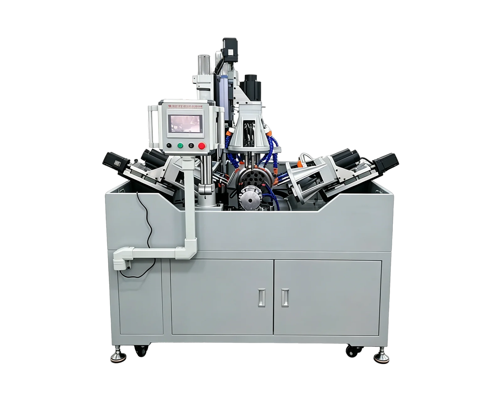
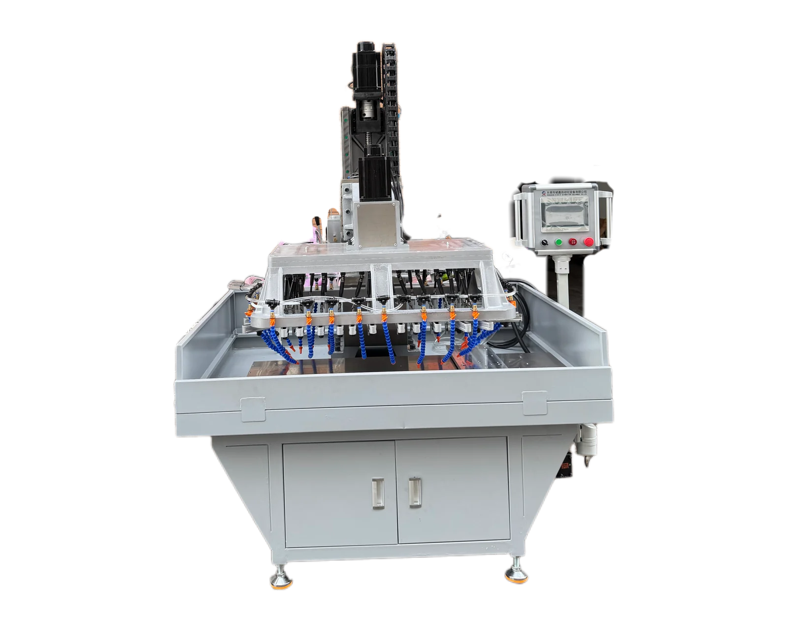
Compare a servo-traverse platform when hole groups require several positions along a member, and a multi-side concept when the reviewed process needs approaches from different faces. These are directions for application review, not confirmed tube-machine configurations. A square tube does not automatically require four machining sides, and opposite-wall features do not by themselves prove that a double-head arrangement is suitable.
For a BINSING inquiry, email the finished drawing, incoming profile specification, labeled section views and production mix. Ask the response to list the covered walls, machining approaches and any repositioning, alongside external cleaning, finishing and inspection work. Use the thin-wall workholding guide for contact and released-part checks, and the long-profile guide for coverage and support along the length.