Explore equipment for your inquiry
Automatic Drilling & Tapping Machines →Compare standard platforms and custom layouts, then prepare the part and production requirements for your quote.
Separate four meanings of machine type
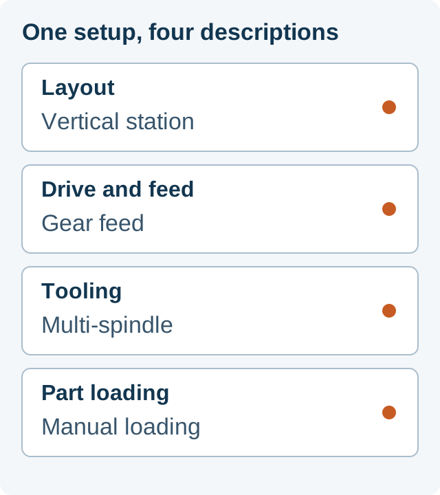
Arm, vertical, servo, multi-spindle and automatic describe different features. A list that places them side by side as mutually exclusive choices hides useful combinations. Describe the proposed machine in one sentence: where the tool works, how rotation and feed are provided, how many holes are addressed, and who or what loads the part.
The diagram is a hypothetical combination, not a supplied-machine specification. The table shows what each classification tells you and what still needs a separate decision.
Choose the layout around the part
An articulated tapping arm supports the tool as it is brought to holes within the arm's working envelope. For a large component with dispersed accessible holes, start by checking whether the tool can reach every required position while the part remains supported. Check orientation and workholding as well as nominal reach. ROSCAMAT's official range includes electric and pneumatic articulated tapping arms; those drive choices sit within the arm category.
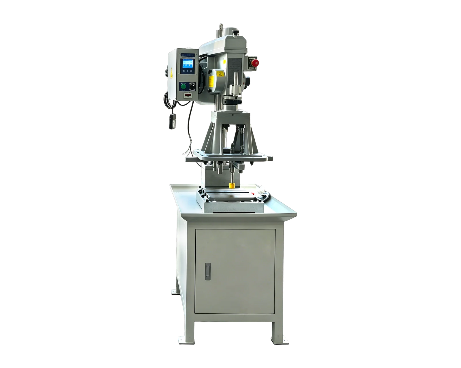
A dedicated vertical station brings tooling toward a defined fixture from above. It is a candidate for repeated parts with accessible holes on the presented face. Sketch where the part sits, how it is clamped and which features the tool can reach. Vertical describes the approach direction; it does not establish thread capacity, spindle count or automatic loading.
An integrated production cell coordinates machining with other stations or handling equipment. Consider this layout when a component needs successive operations, more than one presented face, or controlled transfer between steps. A rotary indexing arrangement is one possible cell layout. It can still have a manual loading station: indexing parts between stations and feeding loose parts into the machine are separate functions.
Distinguish motor power from tapping feed
A motor turns the tool; the feed arrangement governs its advance. Gear-driven pitch feed and servo-controlled tapping describe how the offered machine manages that relationship. Sugino's manufacturer range separately identifies mechanical-feed and servo tapping units, illustrating why the feed mechanism deserves its own classification.
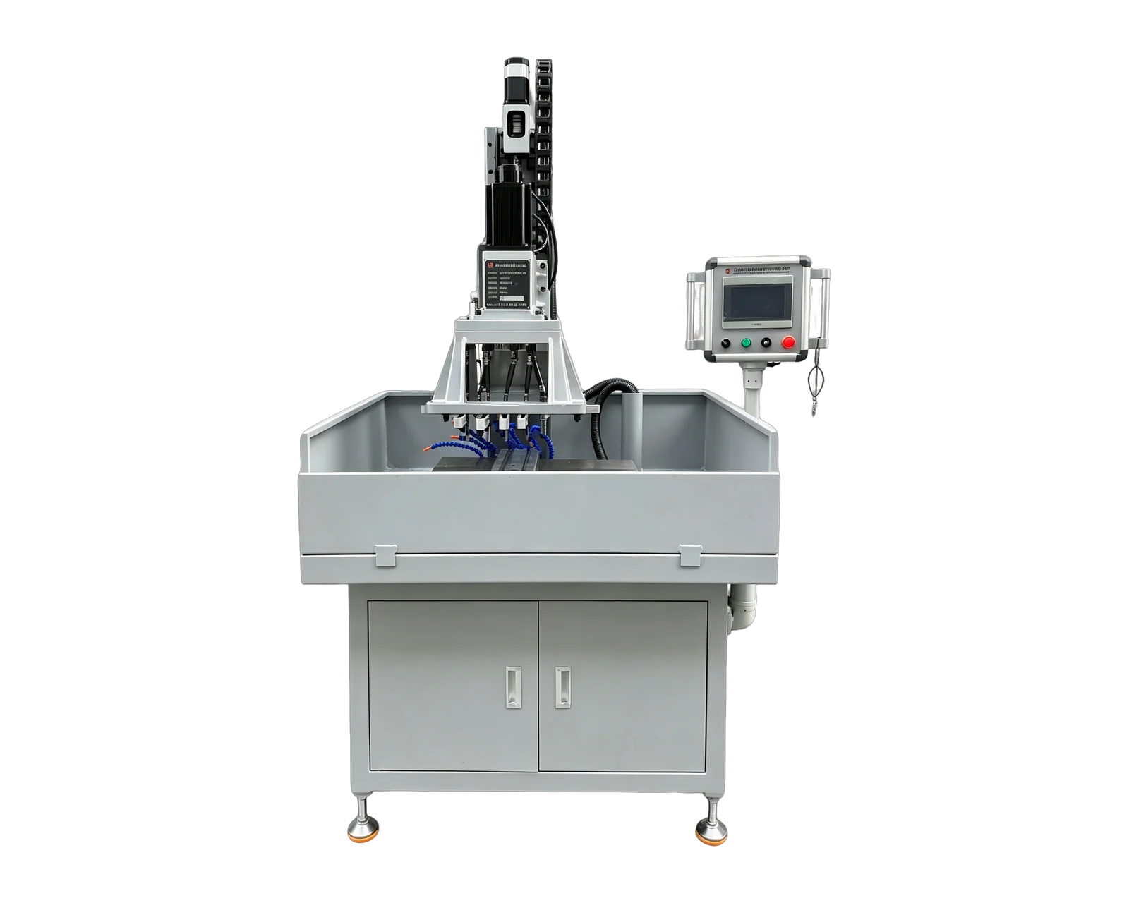
For the BINSING standard range, BX-4508V uses gear-driven tapping feed, while BX-20015 uses servo spindle rotation and servo feed. A stable repeated tapping job in prepared holes can start with the gear platform. A drilling-and-tapping requirement can start with the dual-servo platform. For either route, match the material, thread pitch, depth, hole condition, tools and workholding before selecting the machine.
Pneumatic is also a power description: ROSCAMAT lists tapping arms driven by pneumatic motors. It is not a universal alternative to gear or servo feed, and it does not imply automatic part handling. Compare the actual rotation, feed, control and required utilities. Neither a servo label nor a pneumatic label establishes a general accuracy or production-rate advantage.
Choose the hole arrangement and loading method separately
A single spindle addresses one tool position at a time; additional hole positions need an appropriate positioning sequence. A multi-spindle head groups tools to suit a defined pattern. Sugino's official catalog lists fixed and adjustable tapping heads. Check center distances, tool and holder clearances, approach direction and the load of the complete tool group. Multi-spindle describes tooling, not the number of CNC motion axes.
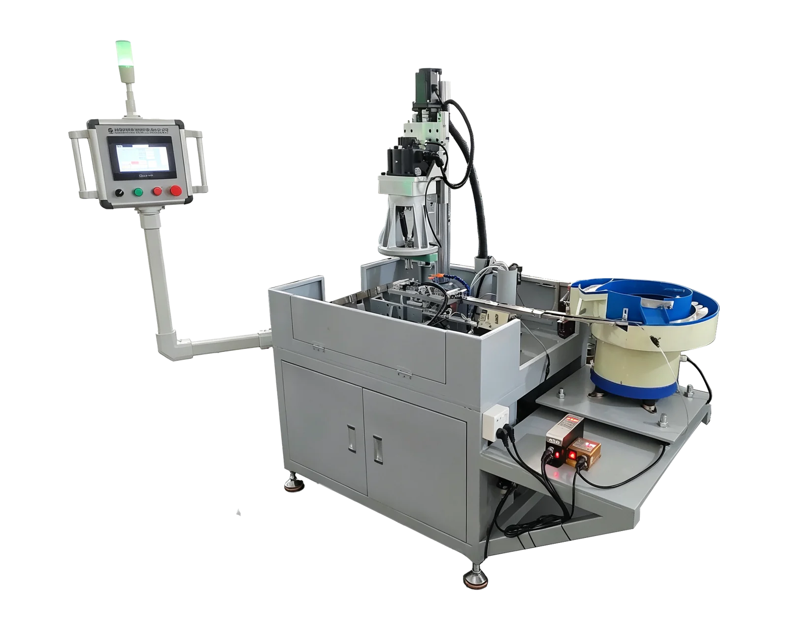
Manual loading can be paired with a powered tapping cycle or a multi-spindle head. Automatic feeding adds a part-handling task: incoming components must be supplied, oriented, located and transferred to the machining position. Specify discharge as well. Replenishment, checks and interruption recovery remain part of the production plan even when transfer is automatic.
Use prepared-hole condition to separate tapping-only work from drilling followed by tapping. For a repeated nut blank, identify the thread operation and incoming geometry first, then assess feeding and discharge together. For a part with several holes, resolve the hole pattern before assuming that a feeder or a larger spindle group will improve the complete process.
Build a shortlist from the actual job
For occasional large parts with scattered holes, investigate an arm arrangement and map reach and orientation. For small repeated parts with prepared holes on one accessible face, investigate a dedicated station and a repeatable fixture. For a stable group of holes, assess a multi-spindle head against their spacing and tool clearances. For successive operations or repeated loose parts, add a cell or feeding assessment to the chosen machining platform. These are selection starting points, not universal performance rankings.
Write down which handling and inspection tasks occur before, inside and after each shortlisted arrangement. Compare acceptable finished parts over the same production period, including changeovers relevant to your product mix. A nominal thread range or a brief cutting video cannot substitute for that complete route.
BINSING's range here covers standard gear and dual-servo platforms plus custom feeding, rotary indexing and other application layouts. The wider classification includes equipment from other manufacturers; it does not mean BINSING supplies every category. The links below lead to the relevant platforms and the detailed arm-versus-station, gear-versus-servo and feeding comparisons.